Yet annother Retroflag NESPi case with Mausberry, Softshutdown, DUO-LED, Momentary switches
-
@jmcfsu13 there are 3 sets of 2 pins. Each set is connected internally. Internally you can switch between the front and center or rear and center. The way it’s wired up by defualt is the power can latch between front and center or rear and center. But only the rear and center are wired up making it act just like a simple on off switch. The reset is a temporary push button that has its internals wires with the front and center hooked up so it’s on when not pressed. so when you press it, it opens and cuts power. I wired it in the opposite pins so it’s open when not pushed in. I hope that makes sence
-
@lostless dude thank you so much, yes that makes perfect thanks.
what i was thinking with the reset is that you dont need to supply 3v to it. The way the basic powerswitch directions work is just by bridging pins 5 and 6 and then scripting to listen for the event. Cant you do the same with the reset button and since you cut all connections to it, just wire 1 side to 5 and the other to 6?
-
@jmcfsu13 i hooked up the reset switch as a pull up. The pin reads 3.3V by default, but you need, from what i understand, to feed a pin set to an input with 3.3 volts to read. I did it that way is so noise can't set off the pin. Its harder for a spike of voltage to go too far down to read low if i'm already at high. Im not using pin 5, but a standard gpio pin like pin 33. I don't know what the difference is between pin 5 and and the others . Maybe someone else can explain that.
-
@lostless said in Yet annother Retroflag NESPi case with Mausberry, Softshutdown, DUO-LED, Momentary switches:
I think you went a tad overboard with the custom pcb breadboard. I just modified the original board by cutting traces.
Well I wanted to avoid solering on a ready setted PCB - these aren't ready for soldering as the solder is lead free and needs higher temps to get liquid. You properly will damage the board and the wire insulation will melt. That does generally looks not clean and the soldering points are very weak towards mechanical stress.
Second point is that you get issues if you perform software shutdown with the mausberry. This switch is intended to be the "captain" of all shutdown. As ES offers a shutdown menu the Pie powers down and the mausberry still provides power and is only useable again if you reset it or cut main power.
To avoid this you need to press the button by remote - via GPIO signal.Maybe other power circuits behave better (@petrockblog 's PowerBlock seems to me the smartest device on the market) and it will be the perfect soultion here because the case offers much space .... so just pack a small PCB topside of the GPIO.
@jmcfsu13 said in Yet annother Retroflag NESPi case with Mausberry, Softshutdown, DUO-LED, Momentary switches:
Im working on this as we speak, waiting on my mausberry to get here. do you have a schematic for your breadboard and pics of the wire layout overall?
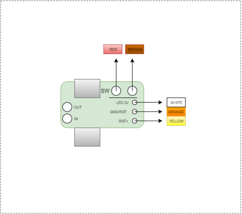
Well I needed 9 connections.
2 for the switch out from Mausberry to switchPCB
2 for the LED out from Mausberry to green-LED (+150R ground) on switchPCB
1 from Pi GPIO to switchPCB to red-LED (don't forget the resistor above or your red LED is dead)
1 from Pi GPIO to Diode to Mausberryground connection on switchPCB (Softwareshutdown)Reset switch shematic is the same as drawn by @lostless
1 RPi 3,3V
1 RPi ground
1 RPi GPIO with resistor (7k-22k)
It set's GPIO via pullip to high and if you press switch the status gets low. So you are waitung for a change from value 1 to 0.The issues with the reset switch resulted as I wasn't able to get clean signal from the Mausberry LED ground... This is a bit floating so I was forced to use the 3,3 power rails from RPi :(
-
@cyperghost said in Yet annother Retroflag NESPi case with Mausberry, Softshutdown, DUO-LED, Momentary switches:
these aren't ready for soldering as the solder is lead free and needs higher temps to get liquid
The trick is to add leaded solder to the mix, then it’s easier to work with. Plus my iron gets hot enough, but been there where it’s not and it’s like working with putty. I’ve been an eletronics tech for 10 years and have done my share of modifying things.
-
@lostless Yes that's true you can solder if you mix with leaded one. But The connection is still not save against mechanical force therefore I used a new PCB and soldered through lugs (??).
This is a high modded switch ...
It has DUOLED support, software shutdown - surly doable with the orginial one but I don't like free wiring ;)
But I think I will make a better solution with an etched PCB. I think I can organize all the needed equipment. -
@cyperghost I don’t I’ll be pulling at these cables so not worried about that. Plus there is a beauty with cables all over the place. Looks more impressive to the technologically ignorant. Lol.
-
@lostless Well it doesn't matter as u usally don't look inside ;)
But I checked your connections - well done ;) -
@cyperghost thx. Not my first project. 😜
-
@cyperghost said in Yet annother Retroflag NESPi case with Mausberry, Softshutdown, DUO-LED, Momentary switches:
My route is much easier as it just used a Si-diode connected to mausberry-switch-ground.
Are you saying you figured out a way to get the Mausberry circuit to cut power after a software-initiated shutdown using just a diode? Can you explain what you did with that diode given the fact that my circuit looks like this:
-
@caver01 If the SW brown is the ground of the switch then just connect any GPIO wire to it. This shutdowns the mausberry.
  GPIO                               MAUSBERRY
from Pie          DIODE            switch ground
   O---------------->|----------------O
I measured a voltage of 3-4V between the switch poles.
The mausberry don't cares of the voltage source.
Is it from the switch or feed from the diode ;)
The diode is just for protection of the Pie against voltage feed-backs.
But the transistor also works.... -
@cyperghost
I see. So you are merely simulating the voltage that would go there if the switch were triggered by supplying that voltage from the GPIO. That makes sense, and definitely easier than connecting a solid state relay or transistor across both switch poles. -
@caver01 Exactly. As the Mausberry mains provides the same ground to all connected devices I see no problem with different ground potentials also. So this should work in general. But it would be nice if you report back.
-
@caver01
I tested with a bare mausberry switch - No Rasperry connected, no LED just the power plug via micro USB.You measure between LED(+) and GROUND Reset Pad >> 0V
Now you connect SWITCH(+) and SWITCH(-) with one cable just for a second to simulate a momentary push button
You measure between LED(+) and GROUND Reset Pad >> 2,5V
The LED(+) simualtes a GPIO output voltage + diode = 3,3V-0,7V=2,5V
Now connect LED(+) to SWITCH(-) (just 1 seconds) and measure between LED(+) and GROUND Reset Pad >> 0VSo this seems to work in general
I used a 1N4002 Diode ... This shuts against 100V and I can provide 1A through ;)
A bit overgrowen but I don't know any cheaper parts...EDIT:
I measured voltage between the switch-pads!
These are 5,0V and if you press the power switch the GPIO will receive back-draws and may get damaged .... So use the diode to protect the Pi - I don't know any cheaper life insurance (and this is a working one) -
@cyperghost @day Word of warning. I think i just burned out my GPIO by my setup and redoing my image without the GPIO script installed in a pull up mode. Even though i had a 10K resistor to lower current, the pin was not set up at that time.. GPIO on any pin is not functioning. Im rethinking hooking up in pulldown mode just to avoid this.found out that the 3.3 volt line is not needed. if a gpio pin is set as pullup, it gives you 3.3 volts on the pin and all you have to do i ground it. i have another issues where the gpio just stopped triggering. on my other card, its triggering just fine
-
@lostless But I think you have to stick to Python. Can you post code please?
-
@cyperghost i will when i figure out whats wrong with my code and why it stopped working. could be something simple as permission issues.
-
@cyperghost @day
ok, come to find out, you don't need to feed the gpio 3V. setting it as a pullup automatically sets it to 3.3V, I guess? its working! so new image of final.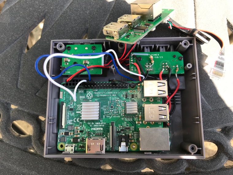
now for the scripting. i want to thank @Heyoeyo for this and helping me understand a tad bit of python. Im using pin 32 so thats been made. change the pin to whatever one you're using. The file is in the home folder called reset.pyimport RPi.GPIO as GPIO import time import os # Define which pin u're using for the reset button (change this to whatever pin you use) resetBtn = 32 # Use 'board' pin numbering (i.e. the zig-zaging numbering scheme) GPIO.setmode(GPIO.BOARD) # See: https://pinout.xyz/ for the pin layout # Set the resetBtn pin to an input and enable the pull-up resistor GPIO.setup(resetBtn, GPIO.IN, pull_up_down = GPIO.PUD_UP) # Define a function which will be called when your reset button is pressed def interrupt_resetBtn(channel): # Print indication to console print "You pressed the reset button!" # Code for detecting/ending an # emulator would go here os.system('/home/pi/exit.sh') # Enable reset button interrupt to trigger on a falling edge (i.e. high-to-low transition) GPIO.add_event_detect(resetBtn, GPIO.FALLING, callback = interrupt_resetBtn, bouncetime = 1000) # -------------------------------------------------------------------- # Now just wait forever for the user to press a button # The sleep time doesn't really matter, make it long enough so it isn't wasting cpu cycles while 1: time.sleep(5)so this just calls for a shell script called exit.sh i made in the home folder. thanks to @meleu for this. (What would do without him?)
# Terminate any emulatorcall!
# This works just for RetroPie!
emucall="$(sed -n 4p /dev/shm/runcommand.info | tr -d '\\"' | tr '^$[]*.()|+?{}' '.' | sed 's/[^ ]*=[^ ]* //g')"
# If there's an emulator running, we need to kill it and go back to ES
if [[ -n "$emucall" ]]; then
    emupid="$(pgrep -f "$emucall" | tr '\n' ' ')"
    pkill -P "$(echo $emupid | tr ' ' ',')"
    kill "$emupid"
    wait "$emupid"
    sleep 5 # maybe it can be lesser
fi
this needs to be made executable, if you called the file exit.sh
sudo chmod +x /home/pi/exit.shnow add to /etc/rc.local
python /home/pi/reset.py &right before
exit 0
reboot andnow the reset can be used to exit back to es. if you want to make reset do something else, remove theimport os os.system('/home/pi/exit.sh')and put in the code you want it to do.
-
This is my mauseberry custom script that seems to be working. Im starting to actually understand this scripting stuff. Thanks to @meleu and @cyperghost and tad bit of me piecing this together form their scripts.
so edit the /etc/switch.sh file after installing the mauseberry driver.#!/bin/bash #this is the GPIO pin connected to the lead on switch labeled OUT GPIOpin1=23 #this is the GPIO pin connected to the lead on switch labeled IN GPIOpin2=24 echo "$GPIOpin1" > /sys/class/gpio/export echo "in" > /sys/class/gpio/gpio$GPIOpin1/direction echo "$GPIOpin2" > /sys/class/gpio/export echo "out" > /sys/class/gpio/gpio$GPIOpin2/direction echo "1" > /sys/class/gpio/gpio$GPIOpin2/value while [ 1 = 1 ]; do power=$(cat /sys/class/gpio/gpio$GPIOpin1/value) if [ $power = 0 ]; then sleep 1 else # End Emulationstation if condition of running binary is true # Thanks @meleu and @cyperghost for 99.9999999999999% of this # Edited by @lostless espid="$(pgrep -f "/opt/retropie/supplementary/.*/emulationstation([^.]|$)")" # Terminate any emulatorcall! # This works just for RetroPie! emucall="$(sed -n 4p /dev/shm/runcommand.info | tr -d '\\"' | tr '^$[]*.()|+?{}' '.' | sed 's/[^ ]*=[^ ]* //g')" # If there's an emulator running, we need to kill it and go back to ES if [[ -n "$emucall" ]]; then emupid="$(pgrep -f "$emucall" | tr '\n' ' ')" pkill -P "$(echo $emupid | tr ' ' ',')" kill "$emupid" wait "$emupid" sleep 5 # maybe it can be lesser fi if [ "$espid" ]; then touch /tmp/es-shutdown && chown pi:pi /tmp/es-shutdown kill $espid exit fi # End Emulationstation if condition of running binary is true (v1.56) sudo poweroff fi doneIf anyone has ideas on how to improve this. Im all ears.
-
@lostless said in Yet annother Retroflag NESPi case with Mausberry, Softshutdown, DUO-LED, Momentary switches:
If anyone has ideas on how to improve this.
yes. Use a proper indentation! ;-)
Contributions to the project are always appreciated, so if you would like to support us with a donation you can do so here.
Hosting provided by Mythic-Beasts. See the Hosting Information page for more information.