Just another Pi in a NES
-
I realized that I had posted in the old forum asking for help, but then never posted my project. So here it is:
Growing up in the eighties I have a special attachment to the NES. Recess and lunchtimes were spent discussing game secrets and strategies. However, over the years I played with mine less and less. Eventually it was put in a box and left in storage in my parent’s house. After I had moved out and to a few different places my parent’s found it while cleaning and asked if I wanted it. I said yes, and my roommate and I played it a bit. At this time I started looking for other games. Things were cheap now, and through garage sales and people from work I ended up with Several NES machines.
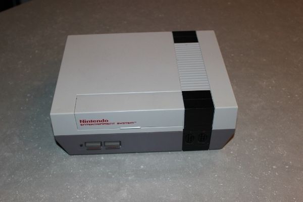
Recently I decided to take the one NES machine in my possession that didn’t work and put a Raspberry Pi 2 in it. I know that I am far from the first person to do this, but I have noticed that most that take on this project end up modifying the case somewhat so that the power connection and HDMI ports are accessible through the side or back. Usually they used USB controllers as well. I decided to take a different approach. I wanted to have the NES appear stock from the outside.
To that end I started by taking apart the NES and removing the stock electronics. I then spent a lot of time cleaning the case. This unit was apparently in the home of a smoker and also had some unknown orange colored gunk in it. I then desoldered the power/audio video output board from the main board. I soldered my own connections to this board such that the component output from the Raspberry Pi was connected to the component outputs on the side of the NES. I also connected my own wires to the power socket.
I then dug through my spare parts bin and came up with some diodes, relays and transistors. I designed a circuit that would energize two relays when the power button is on. Once the Pi boots it holds the second relay on through the GPIO. When the power button is off the first relay is turned off. The state of this relay is monitored by the Pi and when the off state is detected it starts a shutdown script. Once the Pi is shut down, the second relay is turned off, cutting the power to the Pi.
I built my own power supply on the same custom board I put the relays on. When I looked at my NES power adapter I saw that it was a 9V AC adapter, so I built my board to work with that. This means that I have a bridge rectifier to turn AC into DC and a 5V regulator. After testing with a lab power supply I determined that the Pi draws too much current for the original NES power adapter. So instead I found a jack that fit into the power socket and put that on a 9V laptop supply. This provides DC Power which now goes through the bridge rectifier. There is a bit of a voltage drop across the diodes, but it isn’t an issue. It also means that polarity isn’t an issue when connecting power.
Originally I had an old 5V regulator in the circuit, but even with a heat sink it still got too hot. So I swapped it for a switch mode type. It stays cool, but is much larger. To get it to fit in the case I had to mount it at an angle. If I ever redo my interface board I will account for that.
I connected the NES controllers I used the built in gamecon script. This is what I asked for help with earlier.
Finally, I mounted my Raspberry Pi to a piece of styrene left over from another project and the bolted that to the case using a preexisting hole under the expansion port cover.
I have not modified the NES case in any way.


Cheers,
K-Bert -
@k-bert Very nicely done. Interesting to learn that the Pi draws more power than the NES did. I guess modern power adapters are more efficient than the old wall warts.
-
Thanks!
The original NES adapter was just a step down transformer that provided 9V AC to the NES. I'm not positive, but looking at NES schematics I think the alternating current was used for timing in the RF adapter (channel 3 or 4 on the TVs cable input). The circuit board that I've run all my wires to for power in and audio video out used to have the 5V regulator on it that powered the original NES bits.
The Pi is much more powerfull than the original NES. For the increase in proccessing power and speed the electrical power must also be upped. The Pi has a recommended power supply rating of 5V 2000mA. The original NES adapter only has a rating of 350mA (I think).
K-Bert
-
@k-bert
Nice port. About the power supply - which converter did you use? Were you able to measure the voltage? Where there any drains?The NES is powerd by 9V/1.3A AC... that are 1,65A on 5V DC.
Because I want to use a 12V to 5V converter and are asking if they converters in general are not a reliable power source :)
Excuse me.... the 1,3A were for the SNES.... The NES maybe was lower. So it's clear why it not worked, but I think the adapters for NES and SNES got the same power connection.
-
The Nes draws 895ma, but did you use a Mattel nes? Those are rare :s
-
@k-bert question for you. Did you wire up only the red and yellow "composite"? (not component :) ) i used the white rca jack from the rf on the back as the white left audio when i did my buddies nes.
-
I like what you did with the relais, do you mind sharing us how you did it and what you modified in the code?
-
Sorry, I have been away from home for a bit.
cyperghost - I used a laptop power supply from work that was being thrown out. The regulator is a DE-SWADJ 3A Adjustable Voltage Regulator I had that was destined for a project that never came to be.
XVO - Mattel NES are not rare here. Mattel was the original distributor for the NES in Canada.
edmaul69 - You mean composite and component aren't interchangeable? :-P. I set it up to run as the original NES did, so the red and yellow represent sound and video. As all the ROMs I have loaded are mono I didn't bother making it a stereo system. Unfortunately the RF adapter can not be used in the current set up (and I have no intention of changing that).
XVO - I will share what I did when I get to the computer that the code and circuit diagrams are on. I'm afraid it is clumsy and amateurish, but I have no problem showing what I did.
Cheers,
K-bert -
@k-bert yeah the rf is unuseable so i used the white rca for audio. A lot of flatscreens dont support mono correctly so you only get audio out of one of the speakers. If you want better sound even if its mono i would change that. Also component is "red, blue, green, white, red".
-
Alright so here is what I did. I should have used mosfets instead of relays, but I didn't have any spares kicking around whereas I have many relays left over from Arduino 12 volt projects.
The only part I needed to purchase what the female header for the GPIO connection. The NES controllers are wired up as the Gamecon driver suggests. My board simply connects the GPIO to screw terminals to make connecting the wires trivial.
My goal was to have the power button, the reset button and the LED act as they would on the original NES, but I also needed it to safely shutdown and reboot the Pi. I did this with two python scripts that are called at startup.
There are two relays being used. One is the power control relay. This switches power on and off to the voltage regulator. The other is the power button detect relay.
The power comes from my repurposed laptop power supply through the bridge rectifier. The negative DC output of the rectifier is connected to the ground for everything from here on. The positive output of the rectifier is connected to both relay coils. It is also connected to pin 30 of the power control relay. Pin 87 of the power control relay is connected to the voltage regulator such that when the relay is turned on power from the bridge rectifier is sent to the voltage regulator input. The output of the regulator is set to 5V and is connected to the 5V pins on the GPIO.
The side of the coil that is not connected to the positive output of the rectifier on the power control relay is connected to a NPN transistor as well as to the power switch through a diode. The other side of the power switch is connected to ground. So when the power switch is "on" is grounds the relay through the diode and turns on the relay. Alternatively when the transistor is turned on by applying 3.3V to it it grounds the relay through the transistor's emitter, again turning it on. The base of the relay is connected to GPIO 26 which is set to high in my python script. So as soon as the power button is turned on the relay comes on and provides power to the Pi. The Pi boots and then holds the relay on through the transistor. At this point the power button can be turned off and the Pi will remain on.
The power button detect relay's negative side of the coil is connected directly to the power button. Pin 30 of this relay is connected to GPIO 2. Pin 87a is connected to ground and pin 87 is connected to the Pi's 3.3V output. When the relay is turned on by the power button GPIO 2 is connected to 3.3V or a digital Hi according to the Pi. When the relay is turned off it connects GPIO 2 to ground or a digital Low according to the Pi. My script calls the shutdown routine when GPIO2 detects a falling edge.
I found that GPIO26 would go low before the Pi finished shutting down so I added a capacitor to the circuit to hold the transformer on long enough for the Pi to finish shutting down.
Of course I found out after the fact that there is another pin on the GPIO that goes high when the Pi is on and off after the Pi has shutdown which would have made this simpler, but it was too late for me at this point.
Here is the script that does what I described above:
#!/bin/python
#Simpler script for power controlimport RPi.GPIO as GPIO
import time
import os#Use the Broadcom SOC Pin numbers
#Setup the Pin with the Internal Pullups enabled and PIN in reading mode
GPIO.setmode(GPIO.BCM)
GPIO.setup(2, GPIO.IN, pull_up_down = GPIO.PUD_UP)GPIO.setup(26, GPIO.OUT)
GPIO.output(26, 1)#The function that will execute
def Shutdown(channel):
os.system("sudo shutdown -h now")#Add our function to execute when the event happens
GPIO.add_event_detect(2, GPIO.FALLING, callback = Shutdown, bouncetime = 2000)#Now wait
while 1:
time.sleep(1)Now the other part of the equation is the reset button. I was a little unsure how I was going to tackle this. There is the "run" header that many have claimed is a safe reboot for the Pi. I tried it a few times and although it seemed successful it didn't fill me with confidence about being a safe reboot. So I connected a screw terminal block for the reset switch with one side connected to ground and the other connected to a jumper. One side of the jumper would connect the reset switch to the run header and the other to GPIO17. This way if I am ever convinced that the run jumper is the best way to reset I can set it up to do so. I wrote another script very similar to the shutdown script and have it called at startup as well:
#!/bin/python
#Simple script for rebootimport RPi.GPIO as GPIO
import time
import os#Use the Broadcom SOC Pin numbers
#Setup the Pin with the Internal Pullups enabled and PIN in reading mode
GPIO.setmode(GPIO.BCM)
GPIO.setup(17, GPIO.IN, pull_up_down = GPIO.PUD_UP)#The function that will execute
def Reboot(channel):
os.system("sudo reboot")#Add our function to execute when the event happens
GPIO.add_event_detect(17, GPIO.FALLING, callback = Reboot, bouncetime = 2000)#Now wait
while 1:
time.sleep(1)There are a few other components on the board in the form of voltage regulator capacitors and kickback diodes on the relays, but that is pretty much it.
Cheers,
K-bert -
Sorry found and error above. Where it says "...base of the relay..." it should be "...base of the transistor..."
-
Awesome, thanks.
-
@k-bert
The "run" header in my opinion is not a safe reboot at all! It's nothing more than a power interrupt.
I am using it for my builds however, but it's only a last resort to reset the Pi if it crashes. I reboot via the RetroPie menu. Wiring it through your GPIO and calling reboot events is a much more elegant way to reboot your Pi. It's just that i wouldn't know how to, or else i would not use the "run" header myself. -
Feel free to use the method I described above to run a reboot button. All you need to do is install python, use the python code above and edit the rc.local file to call the python code at startup.
Cheers,
K-bert
Contributions to the project are always appreciated, so if you would like to support us with a donation you can do so here.
Hosting provided by Mythic-Beasts. See the Hosting Information page for more information.