Specific questions regarding the powerblock abilities
-
Hi guys, I'm very new to retropie. I have mine up and running, and I found out about this powerblock available, Before go order one, I had questions of how it operates.
1- Will I no longer be able to use the original USB power port?
I ask because I'm trying to get one of those NES cases 3d printed, and will I have to custom cut the case? (Can anyone give me an idea where the new plug will sit? Maybe I can have it pre-printed?)2- Since it covers the GPIO pins, is there a way to attach a fan once the block is installed? I plan to overclock the Pi, and with it inside a case, I really would like to have it cool.
3- How does the switch actually operate? Can I simply turn it off while inside a game, or the retropie main menu? Or do I still need to first go to menu>shutdown, and wait for it to shut itself down before I can turn the switch off?
4-LED: the website states to use a 5v led,.. I have some old LEDs I would like to use, but I don't know much about LEDs or if I have to go buy new ones, could I simply use a resistor?... The specs of these LEDs state:
Vf- 3.2V & 3.3V (I have two different types)
If- 20mA
Vr-5V5- Power Draw: Currently I'm experimenting with different power supplies, and 10ft USB cables. I have some 24awg 6ft&10ft cables, along with some new wall chargers in the mail... Curious if the powerblock is just going to give me more headaches with undervoltage issues?
Thank you again for any help. I tried to write this as neat as possible so that I could have all questions answered.
-
1- Will I no longer be able to use the original USB power port?
I ask because I'm trying to get one of those NES cases 3d printed, and will I have to custom cut the case? (Can anyone give me an idea where the new plug will sit? Maybe I can have it pre-printed?)You need to use the USB power port of the PowerBlock. Otherwise the PowerBlock cannot switch the supply voltage for the Raspberry Pi.
2- Since it covers the GPIO pins, is there a way to attach a fan once the block is installed? I plan to overclock the Pi, and with it inside a case, I really would like to have it cool.
The PowerBlock provides a 5V and GND output pin. You could use that for another relay or so to control the fan.
3- How does the switch actually operate? Can I simply turn it off while inside a game, or the retropie main menu? Or do I still need to first go to menu>shutdown, and wait for it to shut itself down before I can turn the switch off?
The PowerBloc driver initiates the shutdown on OS level. This means that you can turn the switch off and the system takes care for a safe shutdown, you do not need to go to menu>shutdown.
4-LED: the website states to use a 5v led,.. I have some old LEDs I would like to use, but I don't know much about LEDs or if I have to go buy new ones, could I simply use a resistor?... The specs of these LEDs state:
Vf- 3.2V & 3.3V (I have two different types)
If- 20mA
Vr-5VIt sounds as if these LEDs should work. You do not need to use a resistor, the PowerBlock already comes with it.
5- Power Draw: Currently I'm experimenting with different power supplies, and 10ft USB cables. I have some 24awg 6ft&10ft cables, along with some new wall chargers in the mail... Curious if the powerblock is just going to give me more headaches with undervoltage issues?
The PowerBlock uses an ultra-low on-resistance MOSFET for switching the supply voltage. If you have a 2 A+ power supply and a micro USB cable (or another thick enough cable) of good quality you should not have any issue with undervoltage.
-
Thank you for the answers, @petrockblog .
Since the block provides a 5V, does that mean I could hook a 5v fan straight to the board, and just let it run every time I turn the board on? (or do I need to try and run it at a lower 3.3v so its not so loud?)
-
@petrockblog , Have the new powerblock revision switches come in yet?
-
@petrockblog I just received the revision powerblock this week. I want to say thank you, and BTW (I do photography) I was going to take some updated photos of the block installed, for the website?
I'm posting because I still have questions regarding the 5v fan.
You mentioned a relay in this post, and the website mentions a 5v "out" in case you want to use a battery instead of the miniusb.I'm just posting again because I'm confused, and looking for clarification.
Can I hardwire a 5v fan straight to the powerblock, or do I need something inline?
also where do I hook the fan to? The pins marked "5v out", correct?
-
I'm wondering the same thing about wiring a fan to the power block. I think it should be fine, but my knowledge of electronics is extremely limited.
-
@scrappbrapp
Hey - did you ever figure out if a fan can be directly wired to the 5v and GRND output pins? -
@scrappbrapp I would be interested in photos of the PowerBlock - thanks!
Yes, you could hook up a fan at the 5V out pins.
-
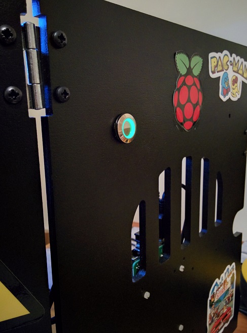
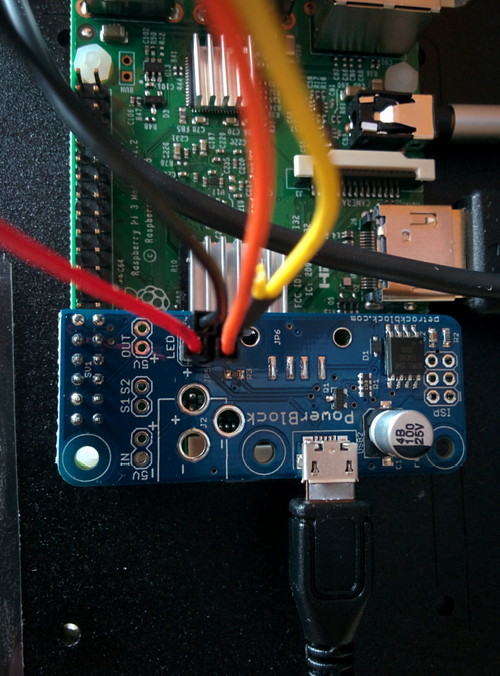
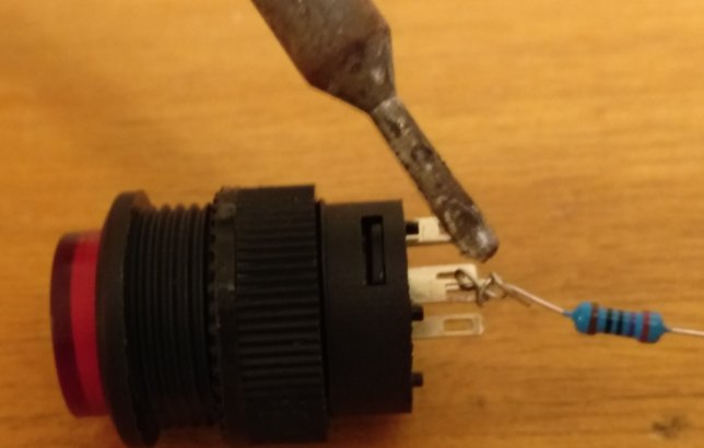
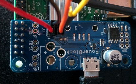
@petrockblog got my powerblock yesterday, very impressed. Here it is in situ.
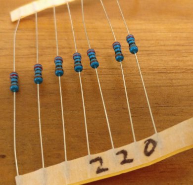
I'm using a latching illuminated push switch for both the switch and the LED. I put a 220 ohm resistor on the LED connection but don't think it's strictly necessary.
-
Revision 1.1 comes with a 22 Ohm resistor so that a separate resistor should not be needed. The additional one does not hurt, of course :-)
-
@scrappbrapp @GtBFilms Any chances of putting together a how-to for your setup? I'm new to the rpi3/retropie world and would love to have a similar setup to what you all described in this thread. Reason being is my rpi3 will be for my family/kids to use and I know that they will not shut down properly and possibly mess things up somehow. I'd like to use a fan to keep the rpi3 cool as well. Any help would be greatly appreciated. Many thanks.
-
@foreverclumsy Hi there, not much to my setup to be honest.
Bought the Powerblock from very reliable @petrockblog -
http://blog.petrockblock.com/2015/07/04/powerblock-another-power-switch-for-the-raspberry-pi/
Arrived in about a week (UK)
Installed according to the instructions on that link.
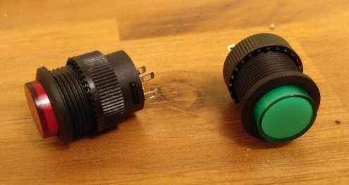
Used an illuminated latching button switch to control it.
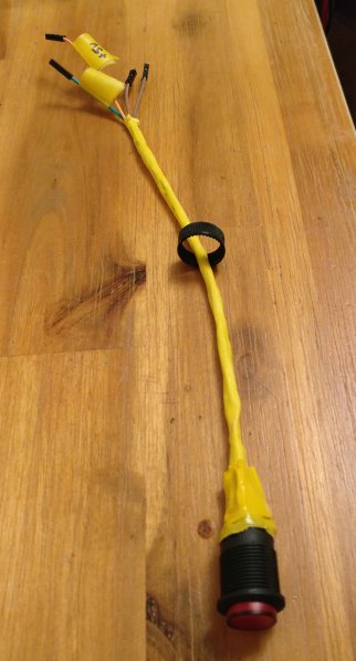
I made up a few of these switches, they are pretty cheap to make, but I've since upgraded mine to a more expensive chrome button one pictured here:
If you want one of my plastic green illuminated button ones, let me know (gtb at gtbfilms dot co dot uk), you can have it for the cost of the postage. I have one with a stupidly long cable and a couple with 30cm long cables (tidier but shorter). They just plug right into the jumpers on the Powerblock. Obviously you need a longer cable if you want the switch to be further away from the Raspberry Pi.
I've got a bunch of red illuminated latching switches too if you prefer, but I'd have to solder you one up.
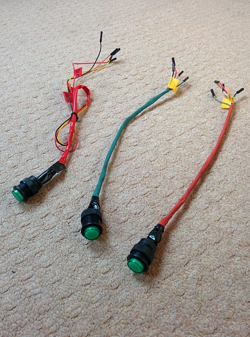
Each switch has four (labelled) connections: +5v and GND for the LED, and the two switch connections - the cables have connectors that just slot right onto the (labelled) jumpers on the PowerBlock board.
I haven't found any need for Rpi cooling fans. I stuck a couple of aluminium heatsinks I got from Ebay for £1 on the chips. Although my Rpi is in a Picade desktop arcade cab, so there's plenty of circulating air, there may be more requirement for cooling in a smaller case with less air flow.
Here's a video of one of those switches in action attached to a PowerBlock - before I drilled a hole in the back of the case to fit it properly.
-
@GtBFilms you are awesome. thank you for pointing me in the right direction. I appreciate the pictures too! i would love a button but think it would cost more for postage to sent to the US! =) i'll see what i can find on eBay/amazon. I haven't attempt to solder anything yet. Slowly taking baby steps!
-
@GtBFilms Have you posted instructions to put together the illuminated latching switches? If not, would you mind sharing? Thanks!
-
@mashtun I'll put something together tonight, there's not much to it to be honest.
-
@GtBFilms Thank you. Wiring is a new step for me, I need all the help I can get.
-
@mashtun Ah, when I said "tonight" what I meant of course, was "in the next few days when I've got through the list of jobs my wife gave me to do"!
Sorry for the delay, I'll try to get it done soon.
-
Sorry for the delay, here's a quick guide to how to create a latching switch for the powerblock.
PREPARATION
You'll need:
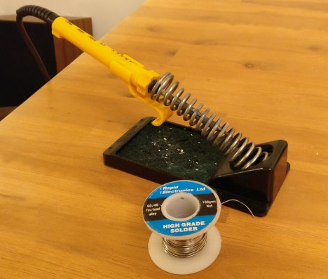
Soldering iron and solder
An illuminated (3V) latching push button switch in your preferred colour:
http://www.maplin.co.uk/p/illuminated-green-locking-push-switch-n05ar (£3.29 each)
or
http://www.ebay.co.uk/itm/5x-Red-3V-LED-Light-Illuminated-OFF-ON-NO-Latching-Push-Button-Switch-Lock-PK-/322314856301?hash=item4b0b76676d:g:zk8AAOSwHMJYGclV (1.79 for FIVE!)You might also like a chrome one, which look nicer but have a premium price, the wiring is exactly the same of course:
Some Dupont Jumper Wire Ribbon Cable (female to female) (of length required, probably 20cm will do)
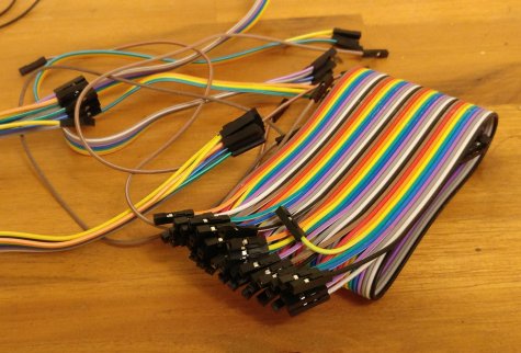
http://www.ebay.co.uk/itm/40pcs-Dupont-Female-to-Female-Jumper-Wire-Ribbon-Cable-Pi-Pic-Breadboard-Arduino-/201615587283?hash=item2ef139b7d3
(£1.89 for 40 wires)A 220 ohm resistor (optional)
Some heatshrink tubing (optional)
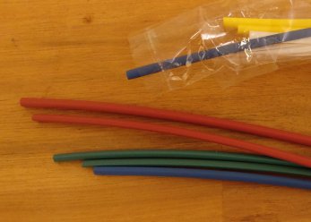
(Ebay, loads of sizes and prices, very cheap).
You'll also need some electrical insulated tape, and a sharpie. For testing, a multimeter and some batteries would be useful, if you want to test it before plugging it into your Powerblock board.
BUILD
Check the back of the buttons, they will have 2 switch terminals and also a positive and a negative terminal for the LED.
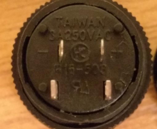
Solder a 220 ohm resistor to the positive terminal. Previously this was required because we were sending 5v to a 3v LED which might blow it. However, the Powerblock is now sensible enough to send only 3v I believe so this resistor is no longer strictly required. I put it in anyway just in case this button gets used for something else.
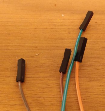
Choose 4 wires from the ribbon cable and seperate them from the ribbon. I recommend using different colours for the LED connections, to avoid plugging them in the wrong way round. The two switch wires can be plugged any way round, they are just a simple switch connection, so they can be the same colour if you like.
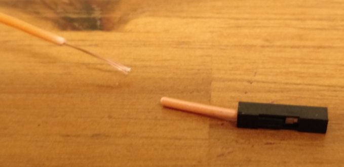
Cut one end off each cable with scissors, strip the plastic covering off (you can use wire strippers or your teeth! (I am not responsible for any dental bills resulting from this suggestion!)), twist the exposed wire to stop it splaying out.
Solder your chosen +ve wire to the resistor, and your chosen -ve wire to the -ve terminal.
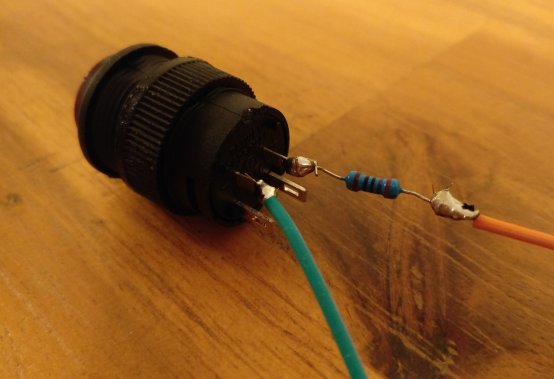
Solder your two switch wires to the two switch terminals.
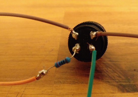
Use some electrical tape between the terminals to make sure they are isolated from each other, then wind the tape round the outside to make the whole thing secure.
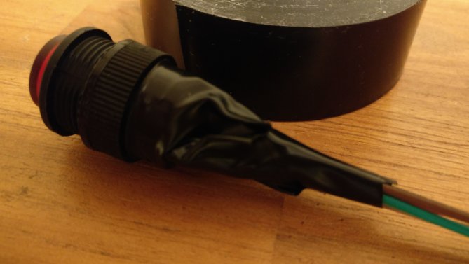
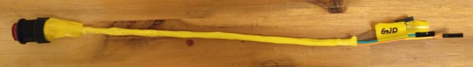
Push all the cables through some heat shrink tubing if required (it keeps the whole thing nice and tidy and less of a spaghetti of loose wires)
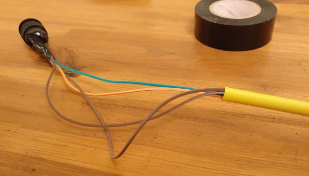
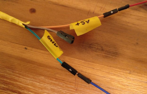
Label the ends of the cables so you don't forget which were the +ve and -ve for the LED:
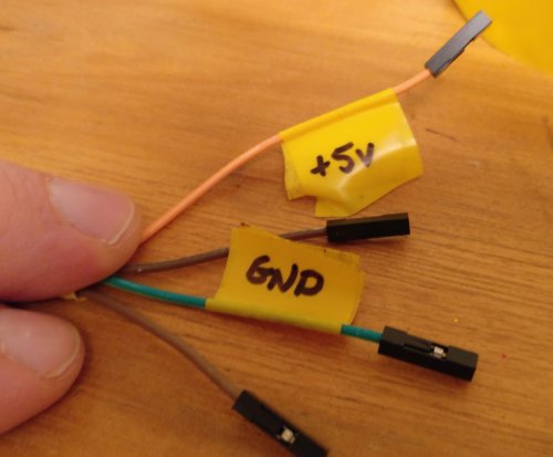
Run the side of the hot soldering iron down the heat shrink tubing several times to shrink it and make the whole thing neat and tidy (if a little bit lumpy). You can also secure the top with more tape, but be careful to ensure the plastic ring on the button can still come off, so that it can be used to secure the button onto a cabinet/case when fitted.
TESTING
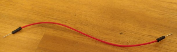
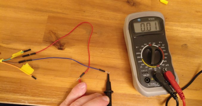
To test it, a couple of these breadboard wires come in very useful, as they can be stuck in the connectors just like the pins on the Powerblock board will go in.
Stick the cables in the two switch wires, and with the switch OFF, check the resistance using a multimeter. It should read 1 (i.e. infinite resistance - the switch is off)
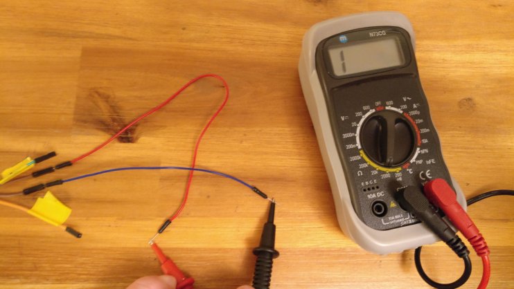
Press the button to switch the switch ON. The multimeter indicates a resistance of 0 (or thereabouts) i.e. no resistance - indicating the switch is on.
So the switch works. Now to check the LED. I use 3 x 1.5V batteries to deliver 4.5V, close enough to the 5V expected.
This time connect the wires to the +ve and GND connectors:
Connect the respective wires to some batteries, and the LED button illuminates:
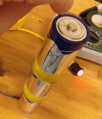
Job done! The switch is ready for connection to a Powerblock!
The LED +ve and -ve jumpers are clearly marked on the Powerblock board, as are the two switch connectors.
Follow the instructions on the Powerblock site to set up the scripts on your Rpi.
Hope that helps.
-
@GtBFilms Fantastic, thank you very much!
Contributions to the project are always appreciated, so if you would like to support us with a donation you can do so here.
Hosting provided by Mythic-Beasts. See the Hosting Information page for more information.