NESPi case, trying to hack in a Mausberry, may have destroyed it, help!
-
I know there are some gurus in here, I hope some of you might be able to help me.
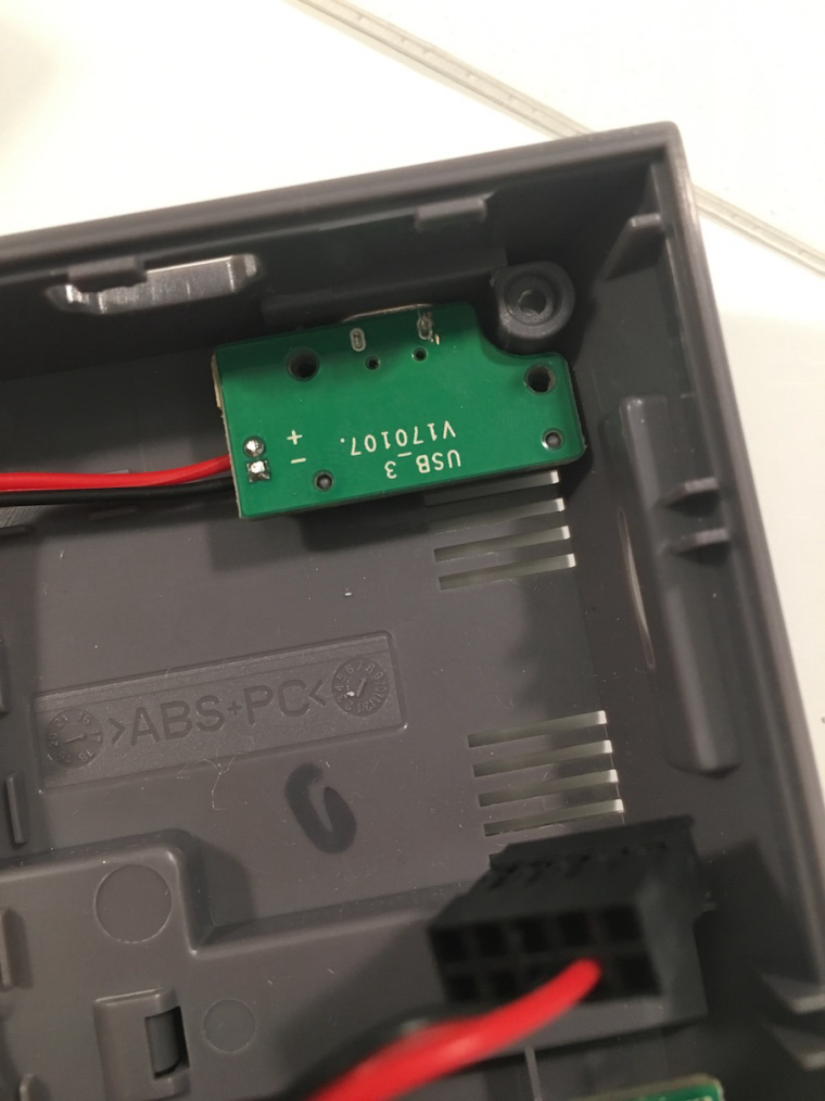
So I've just got hands on a couple of NESPi cases and today I got the Mausberr(ies?) I ordered to use with them. I was inspired by the mosfet hack, but wanted something slightly more finished.
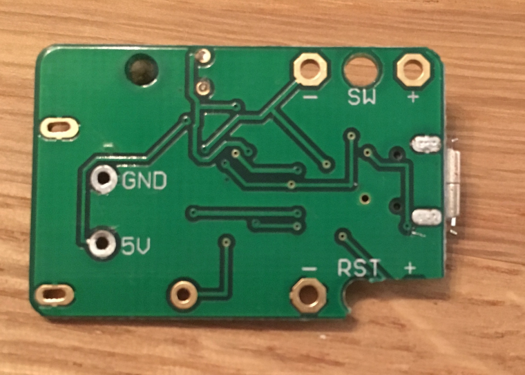
I went straight away with hacking (literally) the Mausberry PCB's, trying to make them fit where the original "POWER" PCB for NESPi case is. I desoldered the large connector, leaving 5V and GND for soldering wires to, and I grinded away the RST + solder pad (AFAIK "RST" only cuts power when holding for 5 seconds, I'd rather like the Reset button to do something useful through GPIO).Original:
Testfit:
Part to cut:

After desoldering and cutting:
The problem;
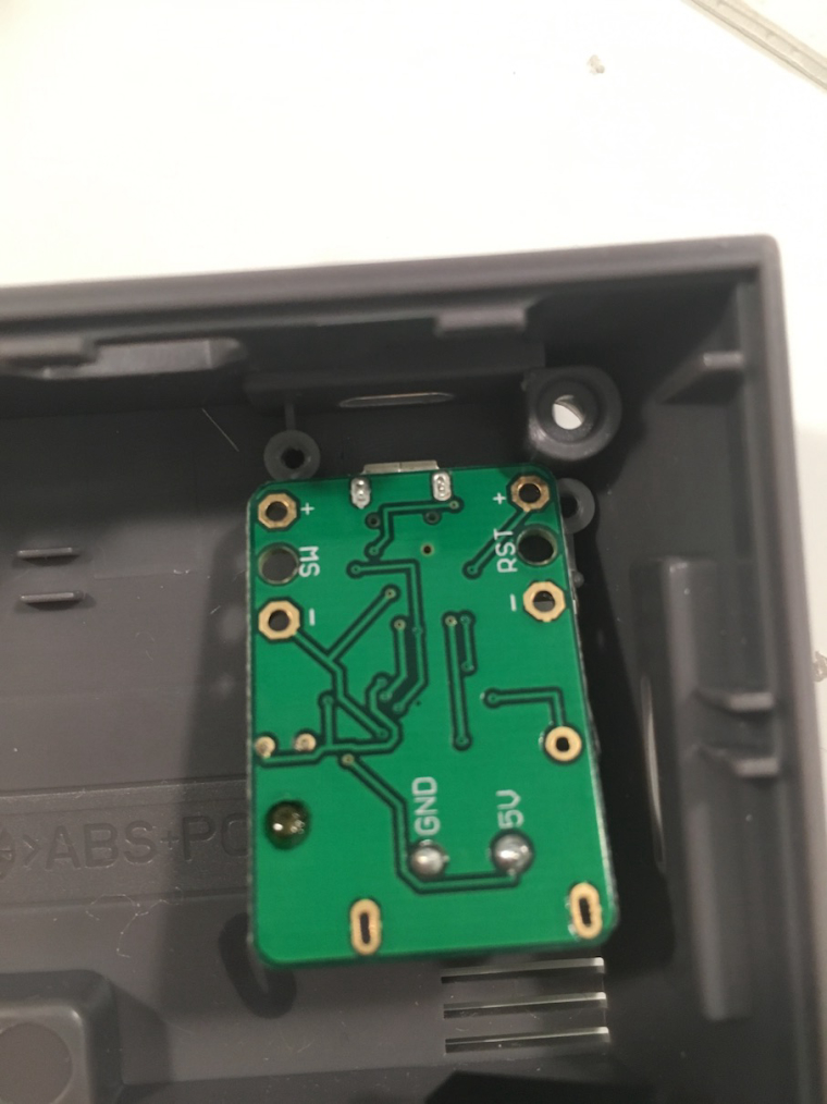
I think I removed to much of the PCB! I removed the whole "RST +" which only had one trace to it (which makes sense), unfortunately I didn't notice a trace on the other side, which continues to a different chip. Now I'm not sure how the Mausberry will work after this is cut, and I was hoping someone could help me out with the circuit, what exactly is the trace I cut used for. I was thinking that it could f.ex. be a pull down resistor, so now I've left the pin floating, but I'm not sure.I appreciate any help I can get guys.
-
@diy_glenn I don't think I would know the answer anyway but my mausberry circuit is a different PCB than yours. Have you simply tried using it yet or are you afraid to before you know the answer?
-
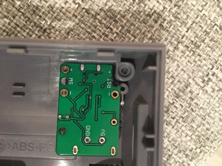
Some more photos explaining the traces, and what I've cut.
Before on the bottom side:
Here's the bottom after being cut:
Here's the trace (going to the pad):
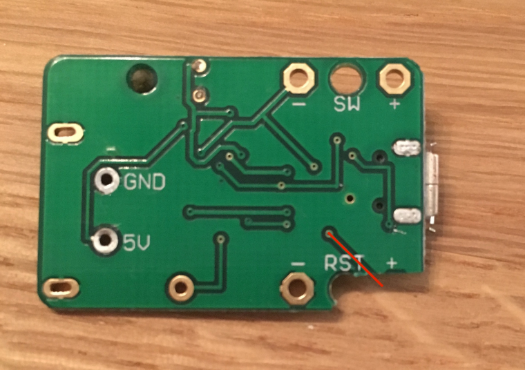
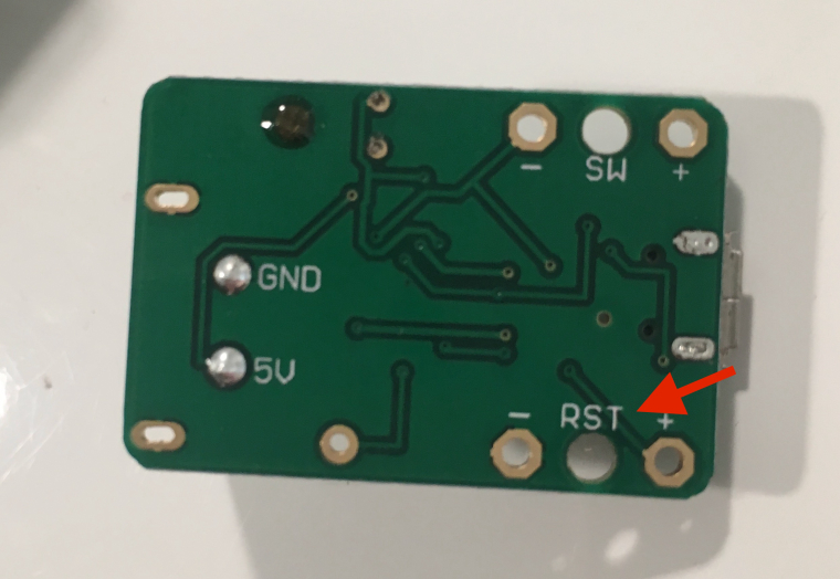
So I only thought about the trace on the bottom side. But there's a trace on top side under the "RST +" symbol as well!
Before on the top side:
After cut:
Possible trace:
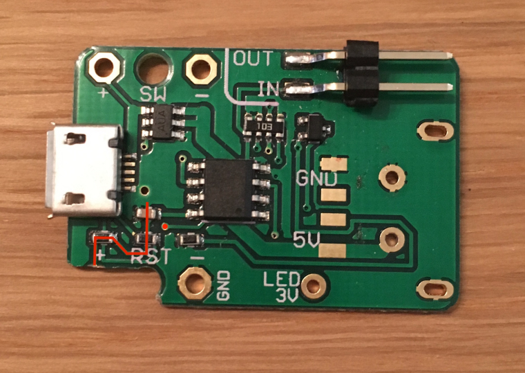
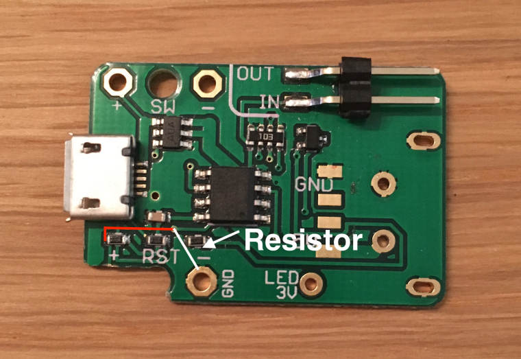
I'm not exactly sure where the trace goes on the top, but it seems like the path drawn is correct, in other words, it's just ground, to a resistor, and then to the "RST +" pad. It seems like that ground path is a bit everywhere just to get the resistors lined up.
So AFAIK, it's a pull up/down resistor...If so, it will possibly give me random shutdowns AFAIK, as it might think I am triggering the "Reset" button. So the fix will be to get that trace connected to the resistor, or add a resistor towards ground.
"Red" is using a tiny wire to solder a new trace going directly, not through the board. White is adding a resistor and connecting to nearest ground.
The funny thing is that I've done this to both my Mausberries, and I'm now crying inside because of my stupidity. Especially if you take a look at the photos from the last post, where I obviously could've remove a lot less, even grinded the plastic a bit to avoid removing the entire pad.
Please guys. Not sure if Mausberry can help me on this.
-
@caver01 said in NESPi case, trying to hack in a Mausberry, may have destroyed it, help!:
@diy_glenn I don't think I would know the answer anyway but my mausberry circuit is a different PCB than yours. Have you simply tried using it yet or are you afraid to before you know the answer?
Yes, I'm a bit afraid to do anything before I can identify what exactly I might've damaged...
It's a great alternative for the NESPi Case, as it fits almost perfectly, just have to glue it down or 3D-print a holder of some sort. -
@DIY_glenn
Just plug it in and see what happens :)
I think it should work.... but nice idea ;)
If you are able to get the reset pad working by connecting GRND and (+) then it's okay ;) -
@diy_glenn Oh, I see now. You think that resistor is connected with a trace back up from the reset pin hole. It does look that way.
-
@caver01 Exactly. It definitely is, I can see the trace from the side of the PCB where I made the cut. I just can't see exactly where it goes. But I'm pretty sure it goes to ground. I'll measure tomorrow when I have my multimeter.
The other thing is that I'll probably not be able to do what I marked in red, that hole is too small! But I could maybe trace out which pin it goes to on that chip, and solder between that and the resistor. Otherwise from the correct chip pin to any ground (f.ex. "RST -").
I'm not that good with electronics, but from what I can see, and what would make sense to be connected to "RST +", would be a pull-down resistor to avoid a floating pin...
-
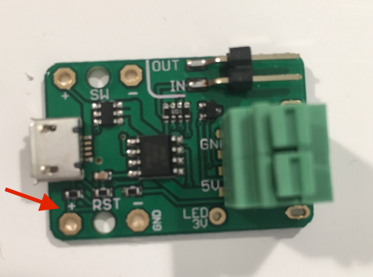
@diy_glenn since it is already a "loss", you could try scraping the enamel off of the entire diagonal trace on the back side. With no components in the way, you might get a good solder if you lay a wire along that line. The wire could be routed up through the "airhole" above the yellow cap.
-
I would think to remove the half of the screw hole before the PCB...
-
Hi DIY_glenn,
I have a the same NESPi case AND the same Mausberry PCB as you, but I gotta say I cant find a way to wire them, so I was wondering, could you please provide a wiring diagram or quick tuto, or even better, a quick and dirty paint picture on how to wire it to the rest of the case ?
That would really be amazing to share it here please !
Thanks for your help.
Best,
day -
-
@jmcfsu13 thanks for your answer however I am not sure I understand how to do the wiring. The post you linked seems to be more of a measuring voltage guide, even if I don't get the part where it seems I should give an 'impulse' to the pi?
-
@day The wiring should be clear but in fact the post here is more a technical how to perform a shutdown via GPIO signal. It's not a guide of measuring voltage ... it's a guide what will happen if you do so :)
I don't get the part where it seems I should give an 'impulse' to the pi?
If you use a momentary switch you give an impulse to mausberry and via gpio the pi can also give an impulse back.
But back to your question:
What's your mausberry version? Is there a switch already installed?
Can you provide a picture or shema of yours? -
@cyperghost I have the same mausberry PCB as mentionned in this thread. And have the retroflag NESPi case which switches I wish to use.
I have no idea how to wire the mausberry PCB to the case so that I case use the switches.
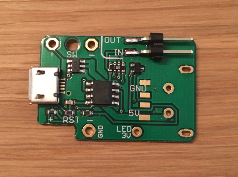
I tried wiring the red and black wires that went to the micro USB PCB from the case (the one OP removed, and did as well) to the SW + and - of mausberry PCB. Then I connected the blue and white pins to the gpio23 and 24, then I wired the 2spring green connector 5v and gnd to the pi3.
Then I plugged the RJ45 and USB extension from the case to the pi3.
I added a fan and the on button would work, fan would turn. Pi3 doesn't turn on however, neither off and reset button.So here I am :)
-
@day You have to cut the traces to the switches or do it like I've done
-
@cyperghost I am not 100% sure of what you did exactly since I do not clearly see on the picture where the wires go to...
also, I do not whish to have the duoled. do you have a simple wiring diagram somewhere ? or maybe explain the "cut the traces" approach along with the correct diagram for that option ? I would be grateful.Best,
day -
@cyperghost I am thinking I need to get one of these cases for my next project, but I don't see why you'd have to cut any traces or even replace the power PCB. Can't you simply follow the traces to the built-in header block and add your wiring there instead of using the stock plugs? Seems like even the Mausberry circuit could nestle in next to the existing power board and you could just run the power wires over to it or solder on a micro USB plug. Maybe the space constrains are too tight? I think I would have to give it a try.
-
@day
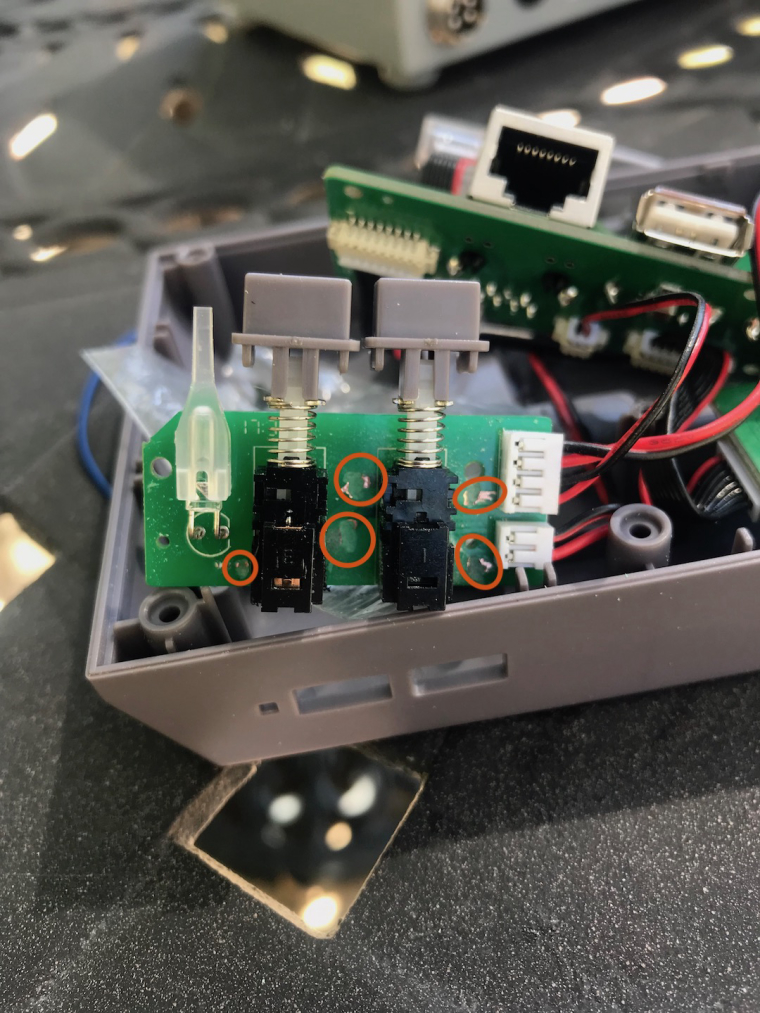
Cut these traces that are circled. That isolates the switches and LED.
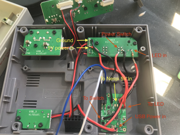
This is how I wired mine up. I hope these help to understand how to hook it up -
@day sorry I meant to post to the thread not a specific post. If you go to the beginning of the thread there is more info
-
@lostless what size resistors did you use?
Contributions to the project are always appreciated, so if you would like to support us with a donation you can do so here.
Hosting provided by Mythic-Beasts. See the Hosting Information page for more information.