My second project--another Nespi case build
-
Back when I built my first pi-based system, the Roadcase Cocktail Aracade, I picked up an extra Mausberry circuit, knowing it would find its way into the next build. I also grabbed a pair of 8bitdo NES30 Pro controllers at a good price on Massdrop a while back. As I pondered the design, I knew this build was going to be a departure from the arcade style and would instead focus on consoles. This would be a truly portable device to be played on the big screen.
Then, Nintendo release the Mini, and by the time the Nespi case appeared I knew what I wanted to do. It is not an original build by any stretch, and the work of others has definitely paved the way for success (advance thanks to @cyperghost @meleu @Yahmez @lostless and probably many others for their work on scripts and/or the Nespi case.
So, here is the first photo of the inside:
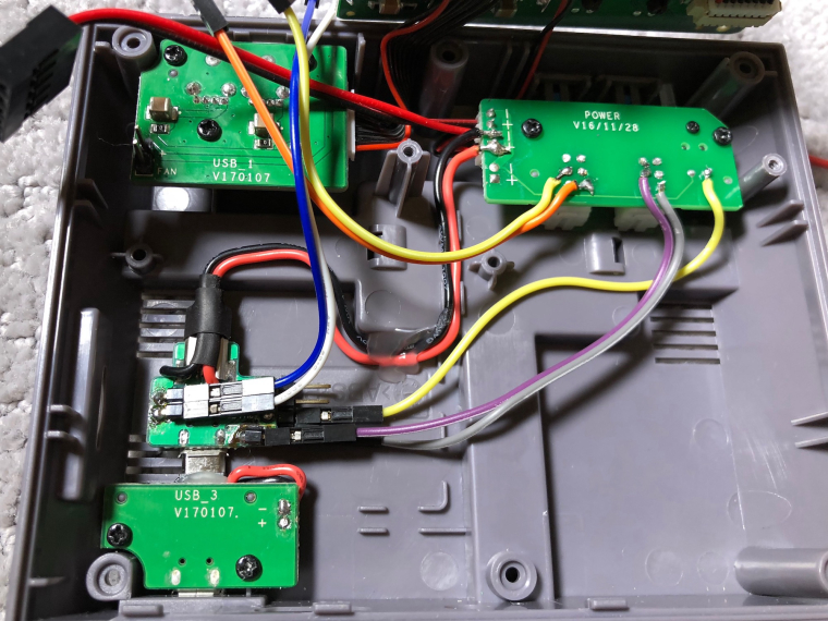
I need to add a resistor to the LED, but I found it convenient that the power board has a trace to ground on the top side which is nice since I already severed the + trace underneath. You cannot see it here, but the switch components are also isolated as others have done by cutting through the traces underneath.
For power, I like the rigidity of the existing micro USB port, so instead of gluing my mausberry into that location and possibly needing to cut into the plastic screw post hole, I desoldered the black and red power line and replaced it with small jumpers to a new micro USB plug that is hot glued to the underside of the power port board. With this arrangement, I can simply slip my Mausberry circuit right onto that.
Most of the work here was around the mausberry. I have all of the connects setup with header pins. These are soldered at a 90 angle so they lay flat allowing me to attach leads for the switch, LED and of course, the IN OUT GPIO leads. I am not using the reset pins on the Mausberry since my reset will simply trigger GPIO and in turn, a script to return to Emulation Station. The hardest part was finding a place on the tiny Mausberry PCB to pull the 5v output power. I found a spot, but it was tight.
NEXT STEPS:
I need to add a resistor for the LED.
I need to connect GPIO leads and setup scripts.
I need to test the RESET function as well as do some tests with the NESPI on/off switch. My previous work with Mausberry used a momentary switch, but this here is a NON-momentary. The Mausberry still works with this switch type, but I don't know if it will behave properly when I toggle the power off. Has anyone tried a Mausberry like mine and the stock NESPI switch? Finally, what about a soft shutdown--what happens when you push the switch after that?
I need to transfer ROMs and do all of the other RetroPie setups.
I need to configure my bluetooth controllers.Lots of work ahead, but this was really the fun part!
-
@caver01 said in My second project--another Nespi case build:
NEXT STEPS:
I need to add a resistor for the LED.Yes, but you can try to connect the LED output provided by the Mausberry (if yours is capable of on LED output??) this delivers 2.5V and there is no need for a resistor.
I need to connect GPIO leads and setup scripts.
Yes but there a tons of scripts here ;) It'll took some time
I need to test the RESET function as well as do some tests with the NESPI on/off switch. My previous work with Mausberry used a momentary switch, but this here is a NON-momentary. The Mausberry still works with this switch type, but I don't know if it will behave properly when I toggle the power off. Has anyone tried a Mausberry like mine and the stock NESPI switch? Finally, what about a soft shutdown--what happens when you push the switch after that?
That's sad to tell you. The behaviour of that switch will work 100% with the Mausberry if you use the button to switch off or switch on. But if you shutdown via software it will exactly act like you know with the momentary push button. The Mausberry will be stuck and needs a hard reset. So even the newest systemd method I showed here won't help. The diode/transistors hacks together with the systemd method will work only on momentary push buttons.
Maybe you can exchange the power button with a momentary one or consider to exchange the reset with the power switch by desoldering the buttons and then put them back :)This is up to now really a clean build. Congratulations! You seem to be very talented in those tasks.
-
@cyperghost said in [My second project--another Nespi case build]
Yes, but you can try to connect the LED output provided by the Mausberry (if yours is capable of on LED output??) this delivers 2.5V and there is no need for a resistor.
I did try powering on briefly as-is. The LED pin on the model I have is 3.3v. The LED is bright (maybe even too bright) so I figured I would tone it down a bit and make it last longer.
The diode/transistors hacks together with the systemd method will work only on momentary push buttons.
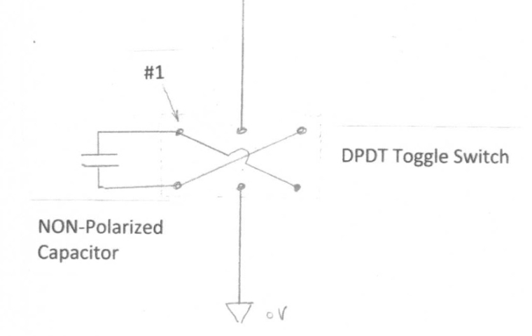
Bummer. I want to preserve the nostalgia with the stock buttons matching the original NES feel. I wonder if I can use a capacitor on the toggle switch and a criss-cross wiring scheme to effectively transform the switch into a momentary. . . something like this:
This is up to now really a clean build. Congratulations! You seem to be very talented in those tasks.
Thanks. Work in progress, but I will finally get to enjoy some real console gaming and maybe some of those fancy overlays for widescreen.
-
@caver01 The hack to convert the NESPi latching switch in a momentary one can be done much easier. Look at the two buttons.... They look like twins. The power switch contains a metal tongue made of copper on it's top, the reset button is without this. The tongue helds down a small metal clamp which will lock the switch.
So remove the copper tongue with a screwdriver and put out the metal clamp. You need literally no force if you push the copper plate towards the button (the one thing with the coil around it).You can easily set the clamp in and add the cooper tongue back to rebuild the switch to originate state if you don't like the behaviour ;)
-
@cyperghost Thanks. You are describing how to simply convert the button into a momentary. That makes sense, and what a clever trick! At this point, I may use it for a while as-is and see how I like it.
I had forgotten how many little tweaks I have done over the years to get things the way I want them. I am attempting to setup scripts similar to @lostless, but I am combining my mausberry script and reset script into a single python script. So far, the shutdown is working, but my reset needs work. More to come.
-
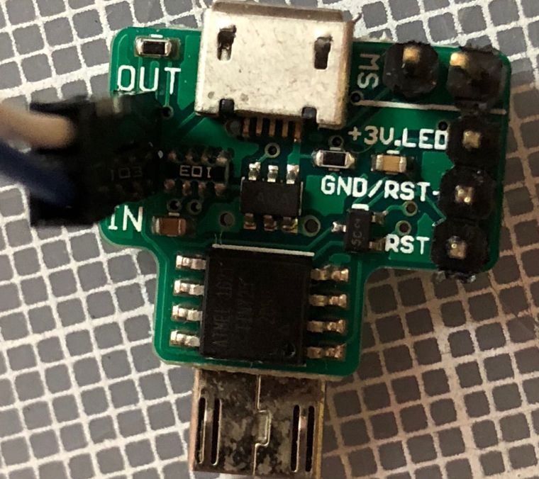
@caver01 About the LED voltage... I measured mine and it delivers 2.6V. If yours is on 3.5V it's a bit rude in design - because you will need resistors. I have two Mausberry with spring headers here....
-
@cyperghost I actually did not measure the LED pin. It is screen printed right on the board with +3V.LED
-
@caver01 Yes the 3V are also signed on mine but I measure 2.5-2.6V.
As I use a duoLED (red and green) in my build this is ideal as I let the green LED glow with an GPIO that delivers 3.3V and the red part is connected to the Mausberry. As they aquaire each round about 10mA but the red LED gots a transmitting voltage of 1.6-1.8V and the green part gots a t-v of 2.1-2.3V I connected one resistor with 100R on the ground with the duoLED and both LED glow very equal and I got a nice orange colouring. See here....So if you measure the voltage and it's 2.5V for a blue, green or white LED you can operate with NO resistor. With red or orange you might need one ;)
-
@cyperghost I added one. I also now have a single python script monitoring the mausberry switch and the reset switch. With python, you can define subroutines for each, then setup edge-detection triggers. For the mausberry, I have the pull-up resistor set to LOW and watching for the pin to go high, and for my reset, exactly the opposite since one pole is attached to GPIO 25 and the other to GND.
This is working really nicely.
-
@caver01 Can you post the script here please?
Would like to use it as I up to now use the bash script.... -
@cyperghost I will when I get home later. It is mostly borrowed from lostless and it is modular in that it makes calls to bash scripts. The benefit is that the GPIO detection is handled by python while still relying on Meleu's shutdown service, or child scripts like killes.sh to close down emulators.
-
@cyperghost said in My second project--another Nespi case build:
Can you post the script here please?
Would like to use it as I up to now use the bash script....Here is the python script I am using to watch both buttons. This script is effectively my Mausberry script and my RESET script:
#!/usr/bin/env python

# Import the RPi.GPIO and OS
import RPi.GPIO as GPIO
import os
import time

# Define which GPIO pins u're using for the Mausberry IN, OUT
# (which are reversed in the script because mbOut comes to pi as input),
# and reset buttons (change this to whatever pin you use)
mbIn = 24
mbOut = 23
resetBtn = 25

# GPIO port setup
GPIO.setmode(GPIO.BCM) # Set pin numbering to BROADCOM GPIO numbering
GPIO.setup(mbOut, GPIO.IN, pull_up_down=GPIO.PUD_DOWN) # Set up pin as an input, pulled down
GPIO.setup(mbIn, GPIO.OUT)
GPIO.output(mbIn, 1) # Set pin value to 1. Mausberry watches for this to change to zero
GPIO.setup(resetBtn, GPIO.IN, pull_up_down=GPIO.PUD_UP) # Set up pin as an input, pulled UP since shorting to GND

# Define a function which will be called when Mausberry switch is triggered
def interrupt_mbShutdown(channel):

        # Print indication to console
        print "You pressed the power button!"
        # Code for shutdown would go here
        os.system('sudo shutdown -h now')

# Define a function which will be called when Mausberry switch is triggered
def interrupt_resetBtn(channel):

        # Print indication to console
        print "You pressed the reset button!"
        # Code for reset would go here
        os.system('/home/pi/bin/exitemu.sh')


# Enable shutdown switch interrupt to trigger on a raising edge (i.e. low-to-high transition)
GPIO.add_event_detect(mbOut, GPIO.RISING, callback = interrupt_mbShutdown, bouncetime=1000)

# Enable RESET button interrupt to trigger on a raising edge (i.e. low-to-high transition)
GPIO.add_event_detect(resetBtn, GPIO.FALLING, callback = interrupt_resetBtn, bouncetime=1000)

# --------------------------------------------------------------------

# Now just wait forever for the user to press a button
# The sleep time doesn't really matter, make it long enough so it isn't wasting cpu cycles
while 1:
        time.sleep(5)
This gets called from my /etc/rc.local
It also relies on the exitemu.sh which is a bash script that leverages insights from all of the previous work to kill the PID for whatever emulator might be running (returns you back to ES). I am just using the same script @lostless posted a while back. You could also just issue a sudo reboot. In any case, the second part I need to add is meleu's shutdown service to completely exit stuff when doing the full shutdown.So, I am not doing anything with soft shutdown requiring a diode/transistor. I have not gone that far yet because I am still using a sticky pushbutton instead of a momentary.
Contributions to the project are always appreciated, so if you would like to support us with a donation you can do so here.
Hosting provided by Mythic-Beasts. See the Hosting Information page for more information.