Mausberry Shutdown Circuit NES Build Help?
-
Hey all,
Thanks a lot for your input. My initial thought was to use the manufactures diagram. I think that seems like the best choice especially since the other diagram appears to be from an older revision?
If a different resistor is required would you happen to know what kind? There is no way this would have been already included on the board?
Cheers!
-
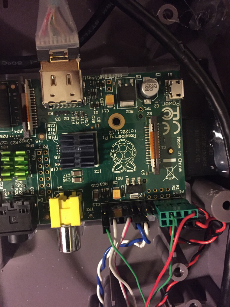
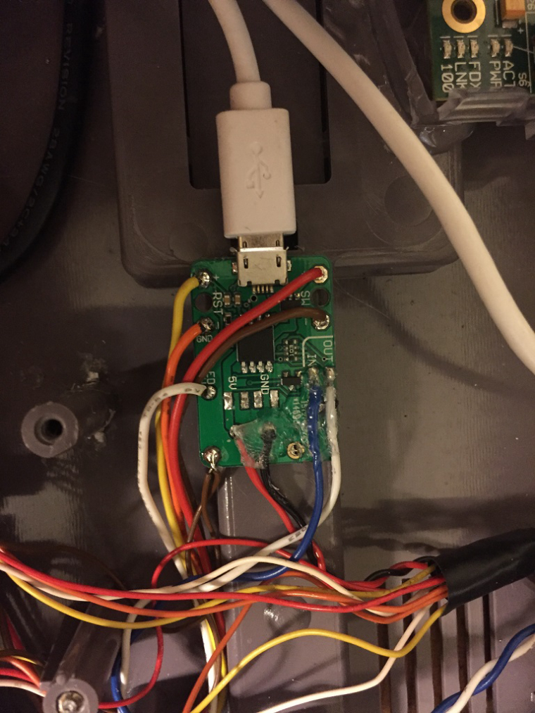
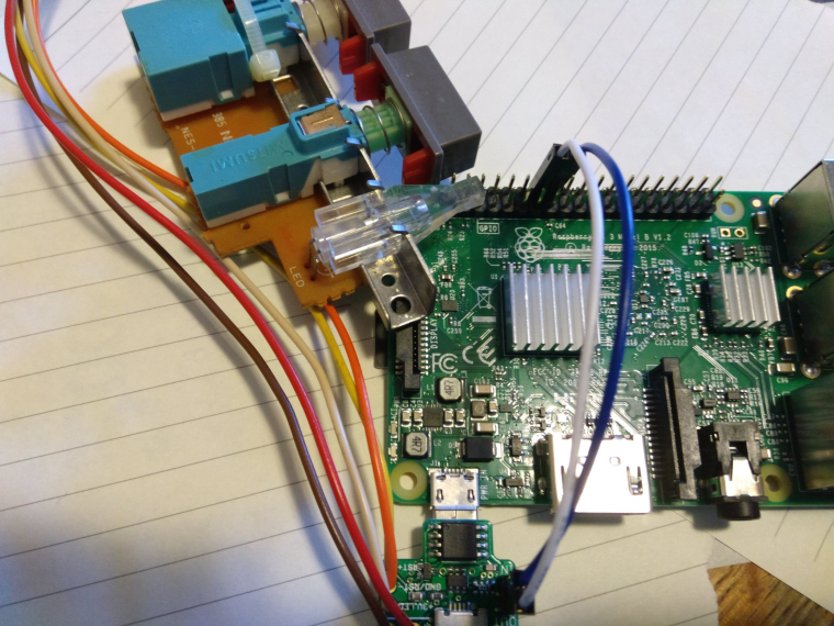
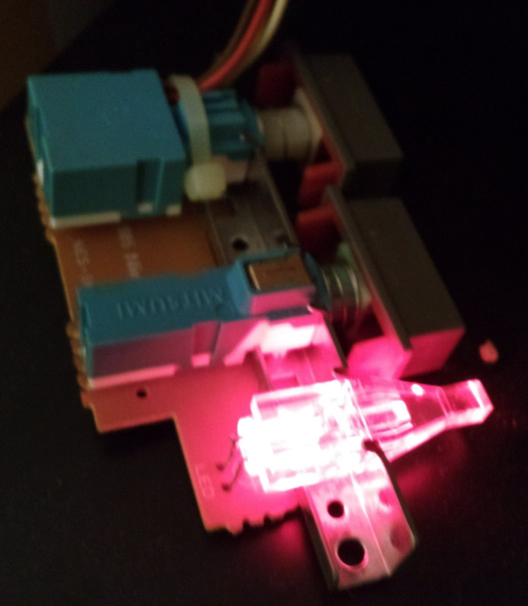
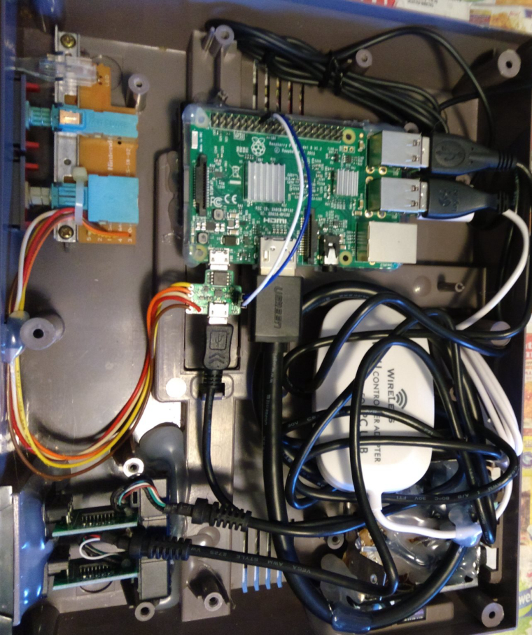
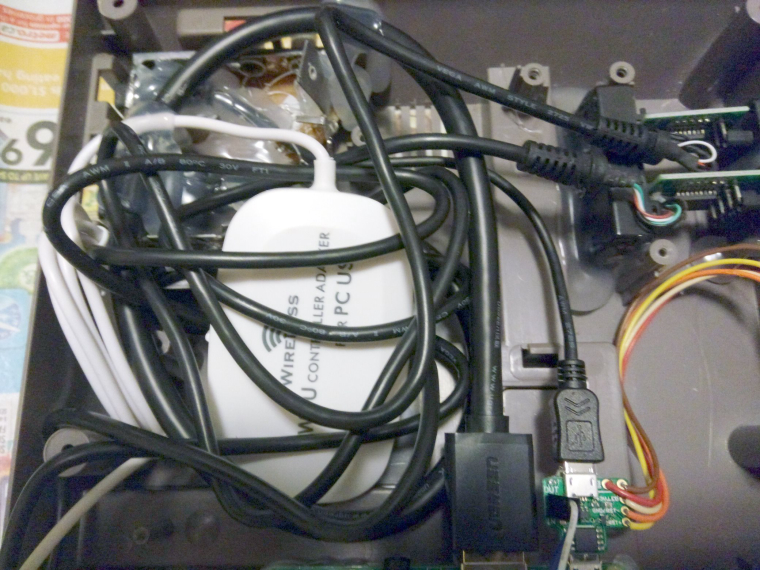
Here you go... From my NES conversion with the Mausberry controller... The only thing I had to do was to desolder the LED and reverse it's polarity (install it the other way)...
-
oh, and pay no attention to the 2 brown wires attached to the bottom of the mauseberry. Those are used for ground connections for the NES controllers (connected to GPIO and using gamecon driver)
-
@jsawhite said in Mausberry Shutdown Circuit NES Build Help?:
oh, and pay no attention to the 2 brown wires attached to the bottom of the mauseberry. Those are used for ground connections for the NES controllers (connected to GPIO and using gamecon driver)
Hey Jsawhite thanks for the pics. I see a lot more wires in your PI. Are these all required for your switch setup?
My switch looks a lot different than yours so still kinda unsure. :)
I'm pretty sure I get where each wire goes from the NES buttons based on the manufacture diagram, however do I still require said resister, and if so which one? This is basically what I'm picturing...
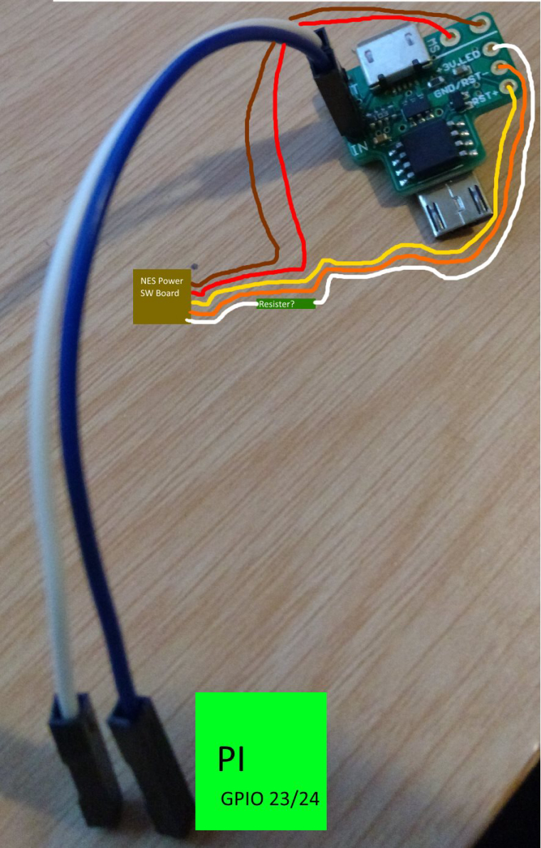
Cheers!
-
Sorry, the extra wires going to the pi are for the NES controllers (I directly connected them to the GPIO). Yes, Mauseberry sells 3 or 4 different variants of the switch, so the boards have a bit different layout. Functions are still the same. No resistor is necessary for this setup. All you have to do is to reverse the polarity of the LED and you're done... :)
oh.... wait... you know what. I think I may have cut a trace on the board... let me pull it back apart this evening and I'll update... Hang tight.
-
eh... had a few more minutes this morning, before work and pulled it apart again...
No traces cut on the button board! :) So easy connections (and a LED mod). The way you have the wires drawn should work fine.
-
@jsawhite said in Mausberry Shutdown Circuit NES Build Help?:
eh... had a few more minutes this morning, before work and pulled it apart again...
No traces cut on the button board! :) So easy connections (and a LED mod). The way you have the wires drawn should work fine.
Hey Jsawhite,
Thanks for your help.
So I've gone ahead and connected everything based on what I had drawn. Installed the correct GPIO mappings on the PI...etc.
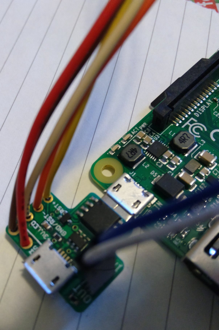
The power switch (and restart) seem to be working great! However the LED does not appear to come on at all. Would you (or anyone) have any ideas? I'm hoping this is a user error and its not a faulty LED. :) I've attached some shots of what I've done below. They didn't all come out as clear as I had envisioned but I'm sure they will do.
Cheers!
-
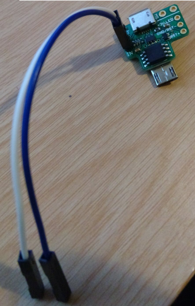
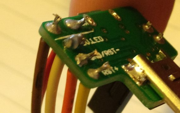
did you take the led out and reverse it's polarity? You have to desolder the led, flip around 180 degrees and resolder it back in place. The current configuration has the positive lead shared with the reset switch. You need the negative. Just be careful you don't bend the leads too much as they can break off the led.
-
Oops I forgot about doing that!! :)
Ok done desolder resolder and now it seems to be working wonderfully. Thanks a bunch!!
Now to wait for the rest of my parts and put it all back together. :)
Cheers!
-
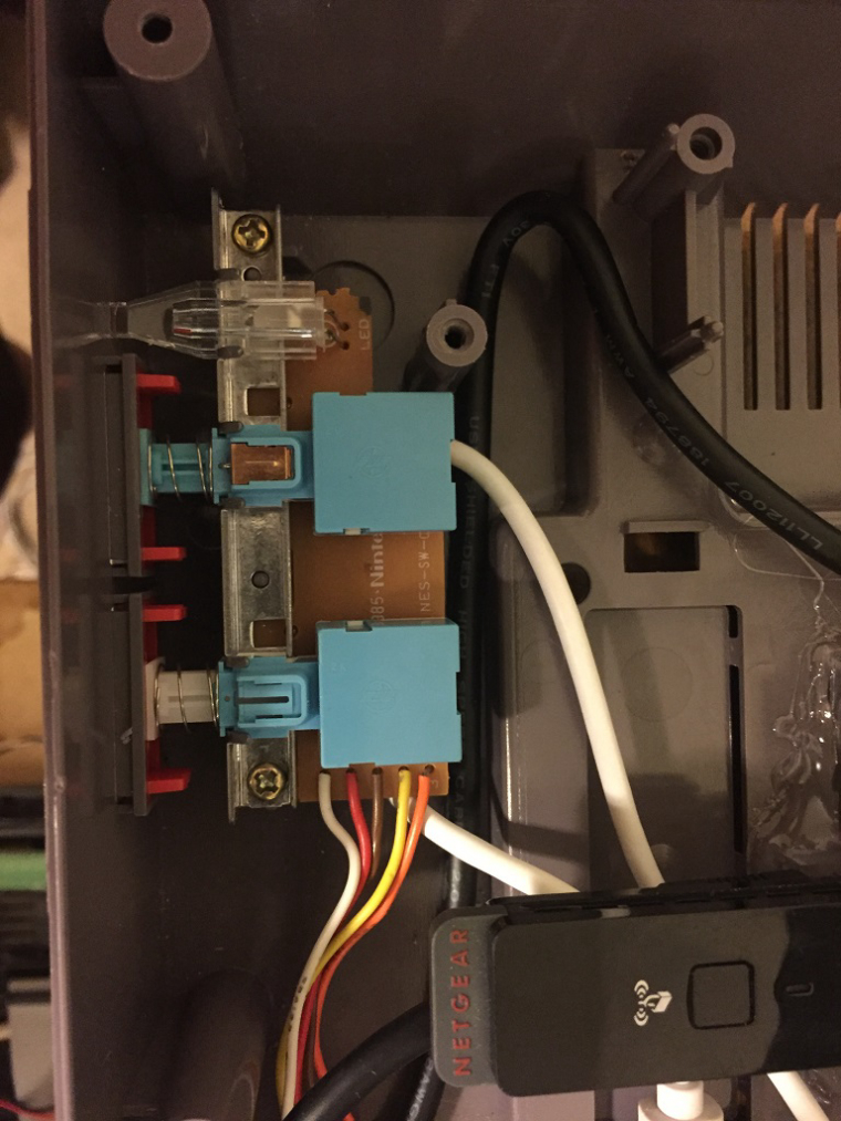
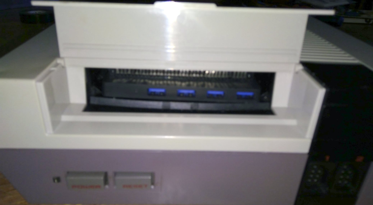
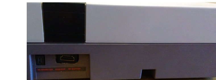
Thanks again everyone for your help. In case anyone is interested this is what I've ended up with...
-Front "NES" ports are NES-USB adapters
-Cartridge bay has a USB hub
-LED, POWER and RESET buttons work
-HDMI and Power in the back
-Wii-U and bluetooth controller capable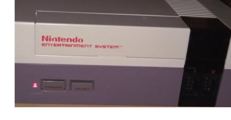
Cheers!
-
hi qwaven can you tell me what tipe of usb adapter did you use and if you use any tipe of driver
-
Hi Elia,
Do you mean for the USB hub? The hub is an Anker Ultra Slim 4-Port USB 3.0 Data Hub and no there are no drivers required.
Cheers!
-
hi, no i mean the nes usb adapter, because i bought this https://www.amazon.com/gp/product/B004L5KHKS/ref=oh_aui_detailpage_o03_s00?ie=UTF8&psc=1
and did not work on retro pie
-
Oh I used Basicest BAS1660 NES to PC USB Retro Converter Adapter for PC and MAC
https://www.amazon.com/Basicest-BAS1660-Retro-Converter-Adapter-Cable/dp/B014R069AI/
I believe there are drivers that came with it for PC...etc but I never installed for the PI. Are you using the latest Retropie/PI v3? If not you may want to try that first.
Cheers!
-
@qwaven yes i have tried everithing, thank man
-
No problem, good luck!
-
Hello, first post and I'm getting ready to complete my nes pi. My question involves the maurberry circuit. Does it matter the order of the brown / red wire connection on the sw? Haza
-
@space-cadet I don't believe so. The switch is just detecting if the circuit is closed. Mausberry has a diagram on their website for NES power connections.
-
I'm about to start my own RetroPie/NES build. I've not quite bought everything I need yet, but I'm working on it. I'm in the process of working out all the details. I have a couple of questions:
-
Is the current model that is available on the Mausberry website different than what they have pictured? Looking at the pictures of their "Use your own switch" model, it looks different than that of the one you have. I'm just curious because if it's different, I'm not going to be able to use your guide, and will have to figure it out for myself (or ask officially in my own thread).
-
Are there any special scripts or programs or anything you need to do to make it all work? I mean, I see you have to connect the 2 wires to the GPIO. Does the Pi need a script or something to initiate the power down, or does it just know via the pins that a signal on them means to power off?
-
Are there any advantages to wiring up the reset button? I was thinking of maybe wiring mine to the "pair" button on a wireless dongle for an Xbox 360 controller. It might be more work than it's worth, so I'm looking for somebody to talk me out of trying it. :) Is it helpful having a reset button?
Who's Scruffy Looking?
-
-
Well to answer your questions.
-
The models look different but are fundamentally the same. I'ts pretty much a layout change and made them more compact. It also included a pad for a 3V LED. You can use the guide.
-
There is script to install but it's so easy to do. the instructions on how to install it are on the Mausberry site. It takes like 5 minutes and even someone like my self who is not very well versed in Linux based systems managed to do it.
-
I'm not sure how you would wire that the way want. But the reset button is pretty helpful especially in situation where the Pi has frozen for what ever reason and you can not use the interface to restart safely. Quite simply what you want to do sounds like more trouble than it's worth.
Hope this helps dude
-
Contributions to the project are always appreciated, so if you would like to support us with a donation you can do so here.
Hosting provided by Mythic-Beasts. See the Hosting Information page for more information.