RetroPie forum home
    • Recent
    • Tags
    • Popular
    • Home
    • Docs
    • Register
    • Login
    Please do not post a support request without first reading and following the advice in https://retropie.org.uk/forum/topic/3/read-this-first

    5" Jumpy screen?

    Scheduled Pinned Locked Moved Help and Support
    jumpylcdscreen
    46 Posts 4 Posters 16.0k Views
    Loading More Posts
    • Oldest to Newest
    • Newest to Oldest
    • Most Votes
    Reply
    • Reply as topic
    Log in to reply
    This topic has been deleted. Only users with topic management privileges can see it.
    • monstermadeofmanM
      monstermadeofman
      last edited by monstermadeofman

      Hey there dude, The screen might not run on 5volt. I've used a back up camera screen for my Gameboy Zero project and I had to modify it to run. Can you post a pic of your drive board.

      I'm assuming you are running from the composite signal

      Not all those who wander are lost

      1 Reply Last reply Reply Quote 0
      • josephchrzempiecJ
        josephchrzempiec
        last edited by josephchrzempiec

        Hello yes a composite signal.

        0_1480080710692_unnamed.jpg

        monstermadeofmanM 1 Reply Last reply Reply Quote 0
        • monstermadeofmanM
          monstermadeofman @josephchrzempiec
          last edited by

          @josephchrzempiec

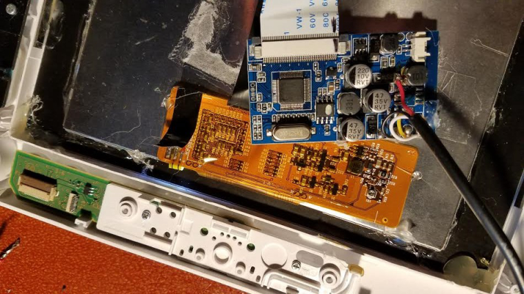
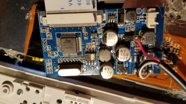
          Can you post a more brightly lit picture, I can't see where you have soldered your jumper wire. I'm not 100% you've soldered the jumper to right place.

          Did you trace it yourself or did you use an online tutorial?

          Not all those who wander are lost

          1 Reply Last reply Reply Quote 0
          • josephchrzempiecJ
            josephchrzempiec
            last edited by josephchrzempiec

            Not much light here I will try to do better. I removed the 1509 chip the 8 pin that converts from 12v down to 5v but i had a hard time solderings that small with my hands shaking So i traced it out and a Diode that is connected to that pin i Solder to. I traced it my self and using my multimeter.

            0_1480081356195_driverboard.jpg

            monstermadeofmanM 1 Reply Last reply Reply Quote 0
            • monstermadeofmanM
              monstermadeofman @josephchrzempiec
              last edited by

              @josephchrzempiec

              Ok. It looks similar to the gearbest screen that I've used just some slight variation in layout. But generally the same.

              alt text

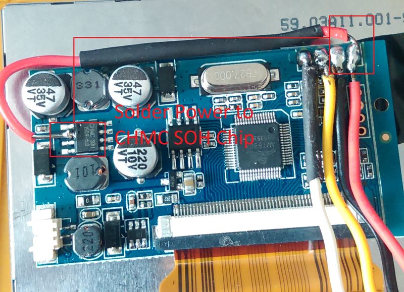
              If you take a look at this baord. The 2nd leg on the chip that is highlighted is where I did my 5v conversion.

              If your chip code matches that I'd suggest working your way from there, the only other thing I can think is your power supply just ain't hacking it.

              Not all those who wander are lost

              1 Reply Last reply Reply Quote 0
              • josephchrzempiecJ
                josephchrzempiec
                last edited by

                Hello same chip 8 pin. The power I'm using is 3.7v 5500mah buck boosted to 5v 2a output. I tested the current from the screen and raspberry pi and total came out to 843ma Way under the 2a mark. The battery pack is good. the thing is i tested a few minutes ago the rear view camera while the LCD was on the battery pack and clear clean video. But when going back to the raspberry pi that is when the problems come in.

                monstermadeofmanM 1 Reply Last reply Reply Quote 0
                • monstermadeofmanM
                  monstermadeofman @josephchrzempiec
                  last edited by

                  @josephchrzempiec What powerboost are you using might I ask?

                  Not all those who wander are lost

                  1 Reply Last reply Reply Quote 0
                  • josephchrzempiecJ
                    josephchrzempiec
                    last edited by

                    Here it is

                    I'm wondering something If there is some noise on the line it's self that is causing this problem?

                    monstermadeofmanM 1 Reply Last reply Reply Quote 0
                    • monstermadeofmanM
                      monstermadeofman @josephchrzempiec
                      last edited by

                      @josephchrzempiec

                      So what are you using to charge the battery? I'm assuming you have a regulator for battery charging? Because all that is, is a step up converter.

                      Not all those who wander are lost

                      josephchrzempiecJ 1 Reply Last reply Reply Quote 0
                      • josephchrzempiecJ
                        josephchrzempiec @monstermadeofman
                        last edited by

                        @monstermadeofman I have a 5v 4a input is my power supply. to 3.7v 1a output charging module.

                        1 Reply Last reply Reply Quote 0
                        • monstermadeofmanM
                          monstermadeofman
                          last edited by

                          Might i suggest making this alot easier by putting it all into one module as I feel you are over complicating the entire thing.

                          alt text

                          http://www.banggood.com/37V-Liion-Battery-Mini-USB-To-USB-A-Power-Apply-Module-p-928948.html?p=9B1915347037201311DI

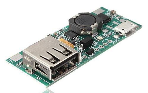
                          This is used quite alot in GBZ builds. It let's you charge and play at the same time. It also has the powerboost built into the board so no need for that.

                          the other option while alot more expensive is the Adafruit Powerboost 1000c

                          alt text

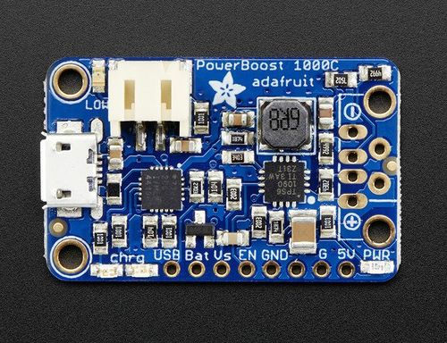
                          Just google it. So many places sell them.

                          Not all those who wander are lost

                          1 Reply Last reply Reply Quote 0
                          • cyperghostC
                            cyperghost @josephchrzempiec
                            last edited by

                            @monstermadeofman
                            I don't want to stop your helping hand but ....

                            @josephchrzempiec said in 5" Jumpy screen?:

                            Hello thank you all for the reply back. It came with a rear view car camera and i tried that. Surely a clear perfect picture no jumping around. It's only in the raspberry pi it's doing this.

                            monstermadeofmanM 1 Reply Last reply Reply Quote 0
                            • monstermadeofmanM
                              monstermadeofman @cyperghost
                              last edited by

                              @cyperghost

                              Yeah I think the issue at this point man is how he's supplying power. Seems a bit convoluted and is probably a power issue if it's ok when just using the camera with it.

                              Not all those who wander are lost

                              cyperghostC 1 Reply Last reply Reply Quote 1
                              • josephchrzempiecJ
                                josephchrzempiec
                                last edited by

                                I want to try something Let me isolate the raspberry pi from the LCD and power it up on a different Power supply and see what happens.

                                1 Reply Last reply Reply Quote 0
                                • cyperghostC
                                  cyperghost @monstermadeofman
                                  last edited by cyperghost

                                  @monstermadeofman Do you think the power regulator is messing the composite signal? That could be possible.... So it should work with separated power supplies.
                                  But it could also be a bad composite connection or a bad config.

                                  josephchrzempiecJ 1 Reply Last reply Reply Quote 0
                                  • monstermadeofmanM
                                    monstermadeofman
                                    last edited by

                                    That's what I was thinking. I'm using a composite screen with with a powerboost 1000C and I'm not getting an issue. But I think the fact he's using individual parts that might not like working together or could be wired incorrectly.

                                    Not all those who wander are lost

                                    cyperghostC 1 Reply Last reply Reply Quote 0
                                    • josephchrzempiecJ
                                      josephchrzempiec @cyperghost
                                      last edited by

                                      @cyperghost And there goes that problem I isolate the screen from the Raspberry pi and just Power the LCD with it's only 5v 2a Power supply and it confirms my thoughts there is Noise on the lines. The LCD comes on with no problem nice and clear and clean.

                                      cyperghostC 1 Reply Last reply Reply Quote 0
                                      • cyperghostC
                                        cyperghost @monstermadeofman
                                        last edited by cyperghost

                                        @monstermadeofman
                                        We will see in the next posting of @josephchrzempiec. Be prepared :)

                                        EDIT: Respect you were right :)

                                        1 Reply Last reply Reply Quote 0
                                        • cyperghostC
                                          cyperghost @josephchrzempiec
                                          last edited by cyperghost

                                          @josephchrzempiec
                                          Nice it works :)
                                          Do you use the same grounding signal for all?
                                          Please then graduate @monstermadeofman

                                          1 Reply Last reply Reply Quote 0
                                          • josephchrzempiecJ
                                            josephchrzempiec
                                            last edited by

                                            Someone Shake my head off my shoulders please LOL

                                            Yes i still keep a common ground between both power supplies bypassing the buck boost converters. As i looked online A lot of these Buck boost converters Because there old design That they are notorious For noise on the lines. I do have a power boost 1000c from adafruit But i do not have other buck boost converter like in your I'm i will look into getting one. Meanwhile i think with a little help from filtering caps might for now Help clear up some of the Screaming noise from the lines.

                                            1 Reply Last reply Reply Quote 0
                                            • First post
                                              Last post

                                            Contributions to the project are always appreciated, so if you would like to support us with a donation you can do so here.

                                            Hosting provided by Mythic-Beasts. See the Hosting Information page for more information.