Powerblock Switch
-
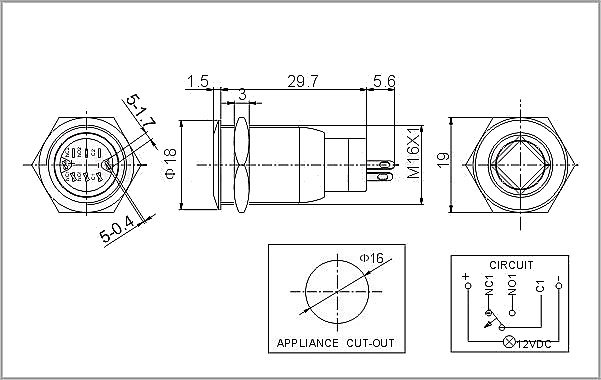
@GtBFilms Thx for the info. 1 more question: i bought the same led button. For the led connection its just the + and - . For the button function to which pin should i solder a wire? There are 3 pins. C1 NO1 and NC1
-
@kverreth Oh yeah, I forgot about that, sorry!
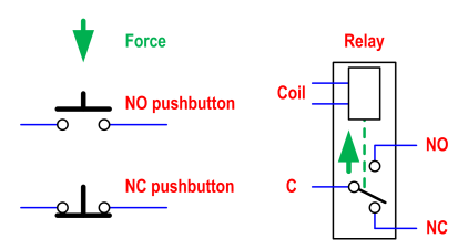
NO1 = Normally open (open = open circuit = not creating a path for the current)
NC1 = Normally closed (closed = short circuit = creating a path for the current)
C1 = CommonSo connect one switch wire to COMMON and the other to either NO or NC.
Which one you choose depends on whether you want to latch the button to turn the power on (the more common approach!) or UNLATCH the button to turn the power on (that would be a bit counter-intuitive I think, but that switch at least gives you the option)
When you press a NO normally-open pushbutton, you provide a path for the current.
When you press a NC normally-closed pushbutton, you impede the current from flowing.So I'd suggest that like me, you probably prefer the conventional approach (push button IN for POWER ON) so want to use C1 and NO1 as the switch connections.
-
@GtBFilms Great! Works like a charm! ;)
-
@GtBFilms said in Powerblock Switch:
@kverreth No worries, I've documented my switch building antics here if you are interested:
https://retropie.org.uk/forum/topic/1771/specific-questions-regarding-the-powerblock-abilities/18
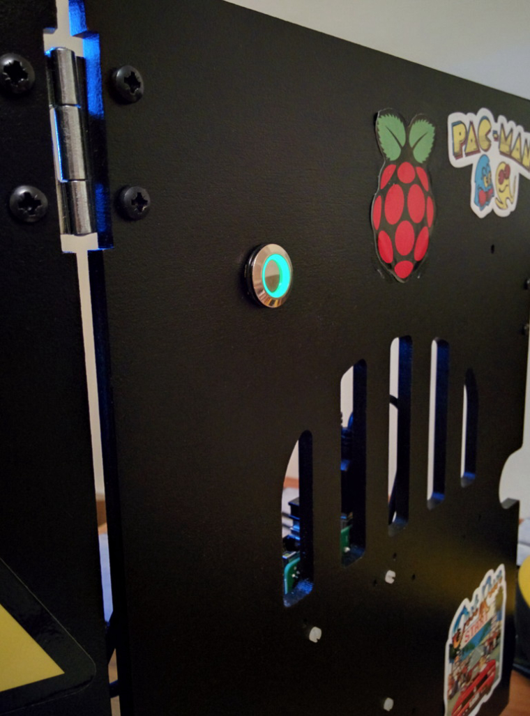
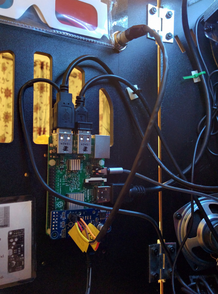
For my own cabinet, I used the chrome button I linked to above (which is how I know it will work!):
This is a great post, thank you for all the detail. I've got 2 ControlBlock's on the way, and want to have a Power Switch waiting for when everything shows up.
Can you confirm that this switch will work properly?
-
@domodan The switch part will work, it's a latching button which is what you want for the PowerBlock, I'm not sure about the LED, the specifications say that it's a 12V LED, and you're only going to be sending 5V to it from the powerblock connection.
However, the listing also says 'LED is rated for 5-12V. ' which suggests it will light at 5V, albeit dimmer than you would get at 12V.
I'd be interested to hear if it does light up, as I looked around for a button with a blue LED but couldn't find any, just red and green ones.
-
So, I was going to hook the switch up tonight by I must be missing something. There are 6 pins. The 1, 2, 3 and 4 pins are double labeled. Meaning when I look at one side a pin is #1, but on the other side it's #2. I can roll the switch from one side to the other (effectively turn it upside down) and the numbers are in the same place even though the pins aren't. Does that make sense?
Also, the + and - pins aren't labeled...I have no idea which is which. If someone could shine some light on what wire needs to be connected where, I would appreciate it. I also can't figure out what the "LOAD" is (represented on the instructions).
-
@domodan There's some instructions on the Amazon item which might shed some light on it, although they are a bit over complicated in my opinion!
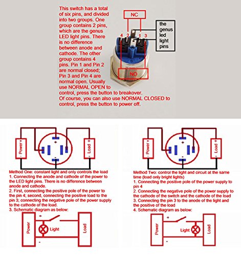
Assuming you want the traditional 'push and latch to switch on, push again and unlatch to power off' (Normally Open) operation, you want to wire the two outer pins (3 and 4) to the switch terminals on the Controlblock/Powerblock.
The inner pins (Normally closed) would give the opposite operational effect.
Regarding the LED connections (labelled 'genus LED light pins), the instructions say 'there is no difference between the anode and the cathode' which seems odd. Unfortunately there are no photos which show the +ve and the -ve terminal, so in the absence of those, personally I'd just test it by quickly connecting a few batteries (say 4.5v) across those terminals one way, and if the LED didn't light, trying them the other way, to determine which way round the +ve and -ve connections are. Then I'd just wire those to the LE connections on the Controlblock/Powerblock.
You don't have to worry about any complicated wiring as detailed in 'Method 1' or 'Method 2' in the instructions - the Powerblock/Controlblock takes care of switching the LED on and off, all you need is a simple switch connection to the outer pins on that button, and another seperate simple connection to the LED terminals.
-
@GtBFilms Try this illuminated push button locking switch from maplin http://www.maplin.co.uk/p/illuminated-blue-locking-push-switch-n06ar - the picture shows green, but it is actually blue (I have one on mine)
-
@GtBFilms said in Powerblock Switch:
@domodan There's some instructions on the Amazon item which might shed some light on it, although they are a bit over complicated in my opinion!

Assuming you want the traditional 'push and latch to switch on, push again and unlatch to power off' (Normally Open) operation, you want to wire the two outer pins (3 and 4) to the switch terminals on the Controlblock/Powerblock.
The inner pins (Normally closed) would give the opposite operational effect.
Regarding the LED connections (labelled 'genus LED light pins), the instructions say 'there is no difference between the anode and the cathode' which seems odd. Unfortunately there are no photos which show the +ve and the -ve terminal, so in the absence of those, personally I'd just test it by quickly connecting a few batteries (say 4.5v) across those terminals one way, and if the LED didn't light, trying them the other way, to determine which way round the +ve and -ve connections are. Then I'd just wire those to the LE connections on the Controlblock/Powerblock.
You don't have to worry about any complicated wiring as detailed in 'Method 1' or 'Method 2' in the instructions - the Powerblock/Controlblock takes care of switching the LED on and off, all you need is a simple switch connection to the outer pins on that button, and another seperate simple connection to the LED terminals.
Okay, cool. So the outer two pins, I can just wire those to the + and - pins on the controlblock? Does it matter which side goes to which pin on the controlblock?
With the genus led light pins, is there any harm in just wiring it up one way, and if it doesn't work then switching it around? I don't know a lot about this stuff, but maybe it doesn't matter?
Thanks so much! I felt like those instructions were overly complicated as well.
-
A switch is a switch, it's either open or closed, so the way round you connect the switch doesn't matter. All that the board (control block or powerblock is checking is that there is a complete circuit from one pin to the other). I'm surprised the control block has them labelled + and - though, I don't think the powerblock does. Are you sure that's the switch pins and not the LED pins?
Theoretically I think you could probably blow an LED by sticking a high voltage across it the wrong way for an amount of time. I never have though. With a low voltage, just tapping the wires to the power for half a second is enough to confirm the led either lights up (and therefore that's the right way round) or doesn't light up (so try the other way)
-
Hi just wondering with the LED ring style button did you managed to get it to work with the powerblock only lighting up the ring when latched on?
Thanks,
Tom
Contributions to the project are always appreciated, so if you would like to support us with a donation you can do so here.
Hosting provided by Mythic-Beasts. See the Hosting Information page for more information.