RetroPie in a Dreamcast VMU!
-
@moosepr Since it looks like you've already got some experience with that particular ILI9163 display would you be willing to share how you attached directly to the ribbon cable? The PCB has a resistor, capacitor, and something else that I can't quite identify, so I'm not sure what they're doing.
-
@moosepr said in RetroPie in a Dreamcast VMU!:
already a few weeks into my latest project
I saw the teaser photos on Twitter. Now I'm curious what else you're up to. Your skill in making PCBs is something I would love to learn.
-
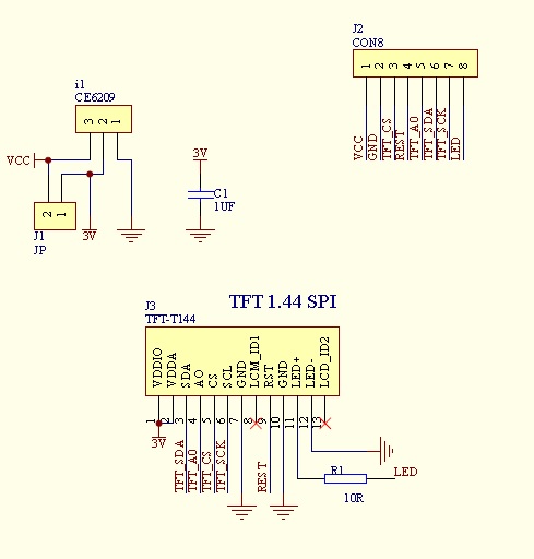
Sure! You will need a 10ohm resistor to tame the backlight, and other than that, wire it straight to the pi!
The boards have a 3v regulator. I can't find an exact data sheet for the screen I have, but most indicate that the screen is OK with 3.3v
Here is the schematic for the little red board

-
@obsidianspider said in RetroPie in a Dreamcast VMU!:
@moosepr said in RetroPie in a Dreamcast VMU!:
already a few weeks into my latest project
I saw the teaser photos on Twitter. Now I'm curious what else you're up to. Your skill in making PCBs is something I would love to learn.
Making the boards isn't that difficult really, the hardest part is getting the schematic electrically correct
-
@moosepr A resistor I can handle. We'll see if I can solder on the ribbon cable without messing it up. I knew there was a reason I bought two. ;)
-
@obsidianspider just be gentle with the heat and you will be fine. Tin the wire, flux the ribbon, and it will soon stick
-
@moosepr do you have a link on how to wire it directly?
Edit: Nm. The page didnt load all the posts. I see it now
-
Hi. Checking in from the other vmu build thread on sudomod ;)
One of the pieces of my puzzle arrived which was a tiny charge/boost board. I'll be doing a bit more of mine soon,but will probably end up doing a custom pcb for it something like @moosepr's PiCB-tft board. -
just a dump of info for anyone venturing down this rabbithole. the screen will run as a st7735, but the driver is trying to do 128x160, so its not ideal!!
it will also run as an ili9163. the resolution is correct at 128x128, but the driver is behaving weird!! it technically runs upside down (chip at the top) and the rotation chops off some of the screen at 180 and 270
if your interested, if you follow my guide in my signature, but replace the contents of
/etc/modprobe.d/fbtft.confwith
options fbtft_device name=fb_ili9163 gpios=reset:25,dc:24 speed=40000000 bgr=1 rotate=0 custom=1 fps=60then you will have a working screen!!!!!1
-
Imagine if the VMU itself could be configured to be fit inside a Dreamcast controller and it would be able to recognize the controller.
Wouldn't that be cool? -
@itsnitro since it doesnt have a select button on the controller you couldnt play super nintendo games. But you could play genesis games.
-
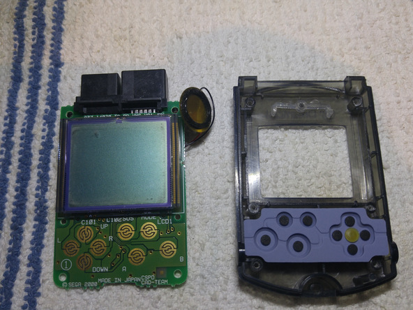
@moosepr I think for the VMU having the cable come out the top will work better (0 rotation) anyway since the buttons will bump right against the screen. Here's an image of the VMU from a teardown on iFixit.

-
I started a build thread to contain the discussion in one spot as I work on this.
-
@obsidianspider and your signature got another icon! :)
-
@ABrugsch Which charge/boost board did you end up getting?
I really need to learn how to make a PCB…
-
PCB making is easy, if you have the chemicals and materials. You can use either a laser jet printer, or an inkjet printer and use a developer and pcb etchant and make your own using EagleCAD software or something to print the board out.
The guy doing this went a bit overboard with the UV lamp and etc, you can do the same thing by sticking the PCB in front of a window during the day:
http://www.instructables.com/id/Creating-Printed-Circuit-Boards-with-a-INKJET-Prin/
-
@obsidianspider said in RetroPie in a Dreamcast VMU!:
@ABrugsch Which charge/boost board did you end up getting?
Uhhhh... A random ebay one that someone in the sudo discord pointed me to. I'll get a link for you but I haven't been able to find a similar one on aliexpress or other shops since.

-
@obsidianspider
here you go: came in about 2 weeks
http://www.ebay.co.uk/itm/252442590514
I haven't hooked it up yet as it only came the other day, but I reckon once the USB A socket has been removed and I replace the 3.0uH inductor with a flat one, then it'll be good to go -
@ABrugsch Thanks! I'm curious as to how it'll work out. I'll keep an eye on your build over at sudomod, and thanks for being one of the first to attempt this.
-
If you are interested in doing it, I actually need to make a few custom PCBs myself. Perhaps I could make a prototype one for you to start off with and see how you like it.
Contributions to the project are always appreciated, so if you would like to support us with a donation you can do so here.
Hosting provided by Mythic-Beasts. See the Hosting Information page for more information.