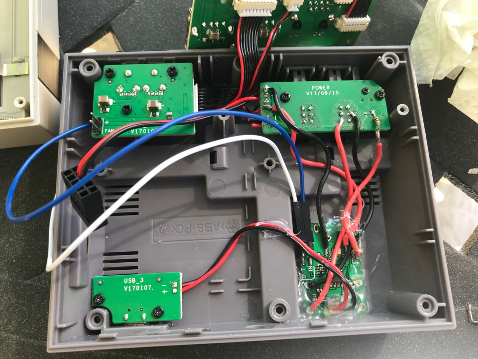
NESPi case, trying to hack in a Mausberry, may have destroyed it, help!
-
@day he’s probably looked at my post on this other thread. https://retropie.org.uk/forum/topic/13361/yet-annother-retroflag-nespi-case-with-mausberry-softshutdown-duo-led-momentary-switches/
-
@caver01 said in NESPi case, trying to hack in a Mausberry, may have destroyed it, help!:
@cyperghost I am thinking I need to get one of these cases for my next project, but I don't see why you'd have to cut any traces or even replace the power PCB. Can't you simply follow the traces to the built-in header block and add your wiring there instead of using the stock plugs?
Yes... buy one! It's really a nice case and worth the money but don't spend more than 20-25$
About the switches. There are two of them a momentary (the reset switch) and a permanent (the power button). If you don't cut the traces then 2 working power switch that can be used like a momentary or a permanent buttons.
So I think it's better to cut the traces and make use of two seperate buttons. But as the mausberry is working better momentary buttons (think about software shutdown) - I rebuild the whole PCB with two momentary units ;)
Seems like even the Mausberry circuit could nestle in next to the existing power board and you could just run the power wires over to it or solder on a micro USB plug. Maybe the space constrains are too tight? I think I would have to give it a try.
Surly the MB fits next to the orginial power input. But then you have to solder directly on the Mausberry without proper pads. Surly it works but I don't like it that way and would always prefer soldering lugs.
I removed the old power unit and dremeled down the old holders. Made a small cut in the column (the first poster here should better do that) and used some small plastic rows as holders fixed with super glue.
-
@jmcfsu13 With cut the traces I ment the traces on the switch PCB not the Mausberry device!
Like @lostless wrote you can see the two ways of building this in the thread here
https://retropie.org.uk/forum/topic/13361/yet-annother-retroflag-nespi-case-with-mausberry-softshutdown-duo-led-momentary-switches/@lostless cutted the traces of the orginial NESPi buttons
@cyperghost rebuilded the NESPi switch PCB -
@cyperghost said in NESPi case, trying to hack in a Mausberry, may have destroyed it, help!:
So I think it's better to cut the traces and make use of two seperate buttons. But as the mausberry is working better momentary buttons
I guess I am looking at that switch PCB and to me it looks like those traces just lead to a little white connector block. Why not just unplug the connector there and tap into the switches using the existing block? The Mausberry I have works with either momentary or regular on/off switches--according to the maker/vendor it auto-detects whichever you decide to use.
Surly the MB fits next to the orginial power input. But then you have to solder directly on the Mausberry without proper pads. Surly it works but I don't like it that way and would always prefer soldering lugs.
I was not thinking of soldering the power directly to the Mausberry, but sticking a micro USB connector on the end and just plugging it in, effectively using the existing power PCB as a mounted port--a passthrough to the mausberry circuit. I think my mausberry circuit is smaller than yours--maybe half the size.
I will have to pick up one of these cases on my own and do a few tests. In the end, It's cheap enough to just modify it by dremeling the post and cutting traces, but I was thinking there were non-desctructive ways to do it.
-
@caver01 Sorry for my bad english
The original state of the power and reset switch do exactly the same. They just cut the power.The original NESPi switch PCB has 6 cabels.
2 for feed in power from the power connector
2 for feed USB Hubs of NESPi case
2 for the switches...So the reset and the power button are doing the same action... They are just cutting power. So you have to cut the traces or rebuild the PCB.
I was not thinking of soldering the power directly to the Mausberry, but sticking a micro USB connector on the end and just plugging it in, effectively using the existing power PCB as a mounted port--a passthrough to the mausberry circuit. I think my mausberry circuit is smaller than yours--maybe half the size.
The mausberry I used is ~ 22x33mm
Of course you can use the orginal power inlet - I considered in doing this, too. But it was easier in preparing the way I did, because you have always to mount the PCB in a fix place and imho it doesn't matter to take the time to do an exact job to fit to the connector hole or just to mount it somewhere :)
But as I said ... get that case ... it's really a pleasure to work with it.Imho the @petrockblog Powerblock is the best power switch for this usecase
-
I'm gonna go with @lostless solution and cut the traces as I understand how to get to this point:

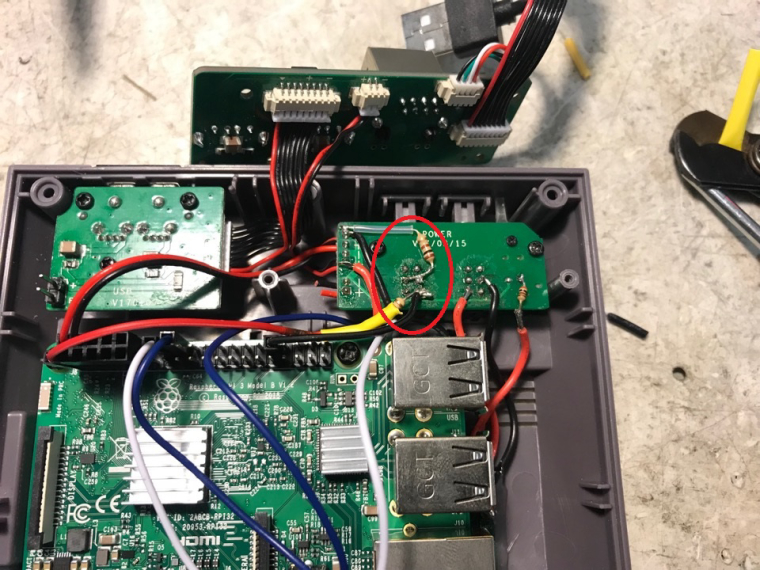
however I dont get how to reach this image :

I circled in red a black wire, a yellow wire and a resistor and I am not sure to where should it be wired...I suppose somewhere to the reset switch.
Also I only see one resistor, and not two like mentionned previously bw jmcfsu13.
And finally, at the left on my red circle, there are two wires that are cut, right ?
-
@day the wires are cut. They went to the mauseberry input.
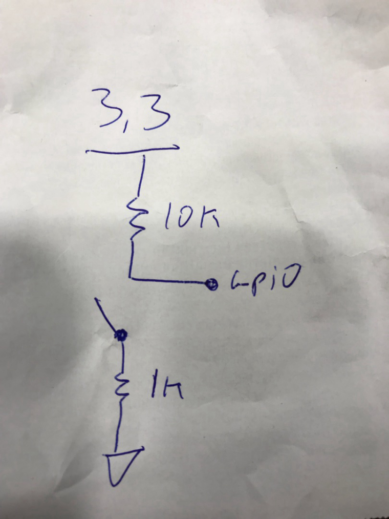
The yellow is heat shrink tubing, to prevent a short with a gpio pin. with a resistor underneath. It’s a 10k ohm going from the reset button to the .3.3v line. Then there’s a wire going from that same location to then gpio pin. Pin 33 to be exact. Then there’s a 1k going from then center tap of the switch to ground. That’s the voltage divider.

A schematic of the divider.
That circuit right there does nothing unless you program it to do somthing. https://retropie.org.uk/forum/topic/13141/gpio-button-to-exit-emulator
Where I discuss programming it. It was working until last retropie update. So trying to figure that out. -
@lostless oh now I got it better ! the color was confusing me, now I see the wires indeed...ok so this is for a certain purpose that you are developping in the thread you just mentionned, its not to have the reset switch do the reset feature then, and it is not mandatory.
which is in fact a good thing since having a real reset would be opposite goal of what we are doing since it wont be a safeshutdown....
very clear now, thanks a lot !! will definitly give it a try tmrw and try to have fun with it !
-
@day I originally programed it to exit any programs and go back to emulation station like the real nes mini exits back to its main menu. Its stopped working after I updated last night, so figuring that out. But it can be set to do anything if you know what you're doing.
-
@lostless which script are you using for the Shutdown part? Mausberry 's?
-
@day im going to continue this conversation on this thread. ill have the script an script for reset there. https://retropie.org.uk/forum/topic/13361/yet-annother-retroflag-nespi-case-with-mausberry-softshutdown-duo-led-momentary-switches/24
-
@lostless I managed to wire the on/off switch like you said (cutting the traces) and add mausberry script and it is working smoothly and perfectly !!! thank you again and again !!! I put the reset button part on hold, the time for me to understand what to do with all the scripts you just posted, but i will continue on the other thread.
-
How about you use the reset on the Raspberry Pi itself?
Contributions to the project are always appreciated, so if you would like to support us with a donation you can do so here.
Hosting provided by Mythic-Beasts. See the Hosting Information page for more information.