MCP23017 and Retropie, some problem appears
-
@stoneset On a breadboard like that above, the power rails do not go all the way along, only half way.
-
So ?
-
@stoneset There are components on both sides of the gap - if there is a gap - on your board.
-
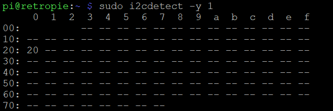
Use
sudo i2cdetect -y 1to get the value for the map figure.What is the resistor connected from 5v to pin 28 for, are you attempting to pull it high? According to the datasheet the chip does this automatically. Also you appear to have the led and resistor connected to pin 21 (up) and the reset pin connected to 5v.
The pinout is as in this image: https://raw.githubusercontent.com/recalbox/mk_arcade_joystick_rpi/master/wiki/images/mk_joystick_arcade_mcp23017.png
-
Hi,
This is my schematics :
Where i have to put the resistor ?
thanks a lot !
-
Okay good news, i have found the problem :
I read this "It uses internal pull-ups of RPi and of MCP23017, so all switches must be directly connected to its corresponding GPIO and to the ground."
So no resistor needed
And, the problem is'nt hardware, but software !
Some pictures :

I think the problem is when i do :
"sudo modprobe mk_arcade_joystick_rpi map=1,0x20"The driver does not work with the mcp23017 and continues to work on the gpio rpi
thanks,
If some one can help me -
@stoneset said in [MCP23017 and Retropie, some problem appears]
I think the problem is when i do :
"sudo modprobe mk_arcade_joystick_rpi map=1,0x20"The driver does not work with the mcp23017 and continues to work on the gpio rpi
thanks,
If some one can help meThis command will make js0 map to GPIO pins as per normal mk_arcade_joystick and js1 map to the mcp23017.
You need to do the following to map it as js0:
sudo modprobe mk_arcade_joystick_rpi map=0x20Why do you have the reset pin on the MCP23017 connected to 3.3V, I've never seen this done.
-
Hi,
Thanks for your reply, finally it work !!
Thanks a lot everyone !(I will write a manual, "how to use MCP23017 on RetroPie")
-
If you want to attach further controllers using addition mcp23017 chips, to can pair all the wires to the Pi and just change it so on of the A0,A1 or A2 leads are pulled high. Then use i2cdetect to find its value and load it using map=0x20, 0x22 (or whatever the address is) and it will connect as P2
I've had 4 players connected like this. Did you leave the reset pin attached to 3.3v? I've just tried on mine and nothing works when I pull that pin high.
-
Hi,
Thanks for you reply,No i didn't leave the 3.3V reset pin on the MCp23017. It work perfectly !
-
Hi @StoneSet
Did you happen to write the manual "how to use MCP23017 on RetroPie?"
I appear to be stuck in the same place you were.
Thank you!!
-
I keep trying to write a detailed manual on this stuff, but have been really busy with work of late.
What is the issue you are having?
-
Hi everyone
@nickstr138 I have created a "driver" for this, check this out :
https://github.com/retrobox/console-modules/blob/master/installinputsdriver.shRegards
Contributions to the project are always appreciated, so if you would like to support us with a donation you can do so here.
Hosting provided by Mythic-Beasts. See the Hosting Information page for more information.