Mausberry Shutdown Circuit NES Build Help?
-
@Captain-Awesome Have you installed the script from the Mausberry setup section of the site? Also, check and make sure you're using the right GPIO pins and haven't miscounted/transposed the in and out wires from the circuit. Those are important as they call the shutdown script and if you haven't installed it, that could also be why it'll only turn on the system.
-
@markyh444
Thank you for your perspective! Yes, I installed the script according to the instructions on the web site. However, I discovered that I had installed the "IN" and "OUT" wires incorrectly in the GPIO header. Here's why:
When I initially built my first NES pi, and then began the second one, I referred to this graphic, which INCORRECTLY diagrams the "IN" and "OUT" wires from the Mausberry switch to the GPIO headers to the Pi:
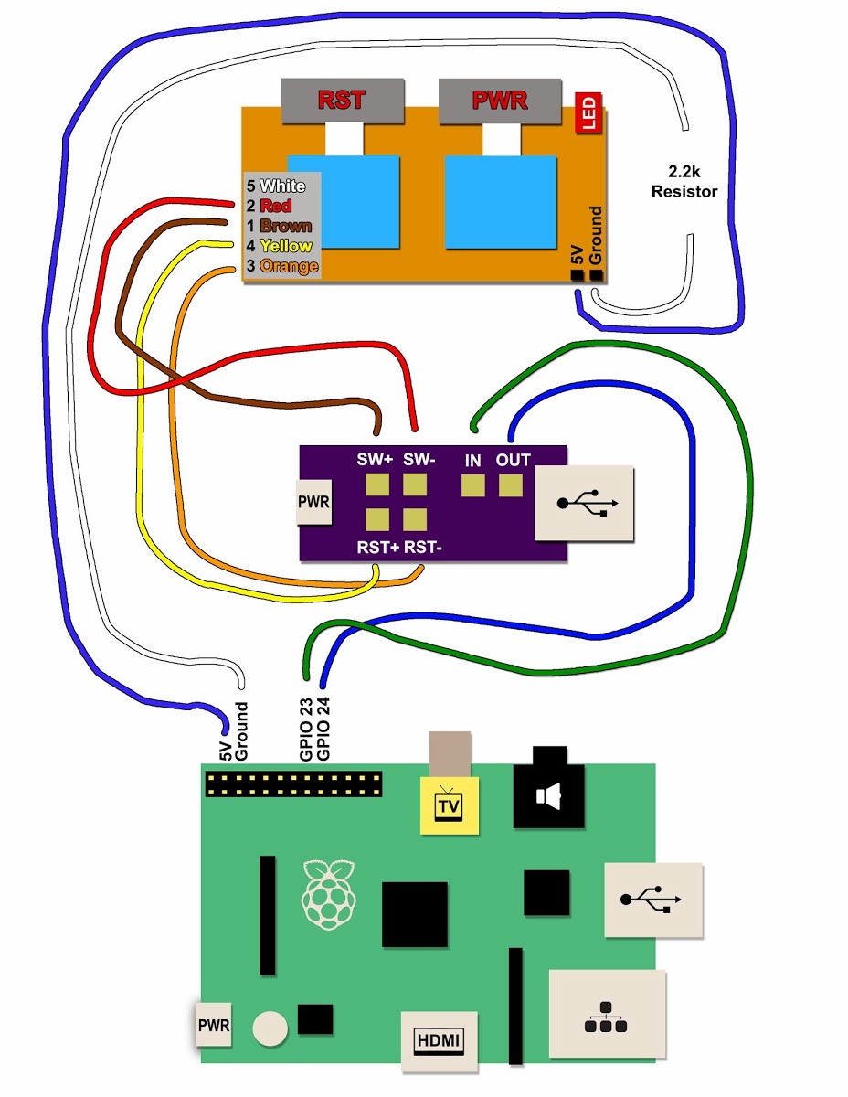
Notice how in the graphic it shows that the green "IN" wire should go to GPIO 23, and the Blue "OUT" wire should go to GPIO 24?
That is backwards, and is what tripped me up in the build process.On the Mausberry setup page, it notes that the wires should be connected in the opposite fashion:
http://mausberry-circuits.myshopify.com/pages/setup
Using the Pi GPIO header diagram at right, connect the "out" lead to GPIO 23 and "in" lead to GPIO 24. If you prefer to use other pins (e.g. GPIO 5 and 6) simply edit the script as discussed later in the setup. Do not connect to a ground or power GPIO pin. GPIO 0 and 1 can sometimes cause issues as well.
Anyways, thanks again for your perspective, since many times when I get stuck on something I just need an extra set of eyes to find the solution. :)
-
@Captain-Awesome No probs dude. I'm the same and an extra set of eyes can spot something you ruled out without thinking, so glad to help.
-
I'm trying to find it but haven't had luck yet...
Is it possible or not to make it where the reset button on the Mausberry circuit has to be held for 5 seconds? Other than that mine works as it should, powers on, safely shuts down, and the LED works as it should as well just the reset button resets it immediately when pressed.Anyone have any input on this? I have tried to make contact with Mausberry but no luck.
Thanks in advance,
Chad -
@happygreens7 Probably. It would require adding some code to the script to watch for a set amount of time to pass before executing the next command. I wouldn't know how to do the programing, but essentially you have:
Watch for Reset Button to be Pressed
Reset Button Pressed
Execute Reset Command
Return to Watching
You'll be adding this:
Watch for Reset Button to be Pressed
Reset Button Pressed
Watch for button being held
Release before timeout?  -> Return to Watching
Timeout reached? -> Execute Reset Command
Return to Watching
But like I said, I don't know how you would actually write that into the script. But I would definitely think it's doable.
-
@Captain-Awesome Thank you for this post, I was having the same issue. The GPIO pins that I looked at online had incorrect number listings, added with the comment about switching the wires from the first image, I was able to get mine running. Without your post (And the really helpful reply) I wouldn't have been able to get mine running! Thank you again!
-
Wow, I used their Web site and the setup section was correct. Can't remember the pin connections but it worked first me.
-
-
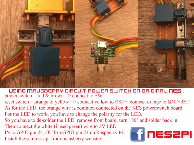
Hello together, thank you for your instructions. Thanks also to japanwings for the plan. I still have a problem with my LED. I have everything connected as according to the plan of japanwings, power and reset works fine, only the LED does not light up. I have also rotated 180 as described. I thought then only, maybe the LED is defective, made a second turn, but this does not light either. I then came to the idea of measuring the current arriving at the LED and this is only 1.5V. Is not that too little? Because on the Mausberry yes also 3V Out LED stands? Has anyone perhaps also the problem or can help me there? Of course there would still be the possibility to connect the LED with resistor directly to the GPIOS of the Pi, I thought I'd ask first. Thank you for the answers.
-
Do a continuity test on the diode if you have a meter
-
Hi, I have a test done with a tester. The LED is lit. I have also tested it with a second LED and lifted it to the soldering points of the white and orange cable, as it did not illuminate. But when I had connected this with the yellow one, it shone. Can it be that the allocation with my NES plug is different? But since the rest so works, I will simply disencade the LED and connect an LED directly to the PI via GPIO.
-
I still notice. When in Emulationstation, e.g. in a game the description changes and a new game scrapt etc. and one presses the Power Button, then this is not saved. If you go to Shutdown System at Emualtionstation, then yes. Is there an experience with it that you have to change something at the skirpt of Mausberry? The first Emulationstation is closed and then the shutdown process begins?
-
So it's definitely like that when you press the power button, the metadata in ES will not be saved. Does anyone have experience in it? That one changes the mouseberry script, which is first closed ES and then the PI drove down?
Contributions to the project are always appreciated, so if you would like to support us with a donation you can do so here.
Hosting provided by Mythic-Beasts. See the Hosting Information page for more information.