Pi in a Gameboy Advance Build - WIP
-
I tried going with the "nuclear option" to get the drive to read by adding
dwc_otg.speed=1to/boot/cmdline.txtand after booting the drive is recognizing, but then the controller wasn't. Thinking maybe I fried the controller with all of my power testing I tried plugging the controller into my laptop and it worked just fine, so lowering the USB speeds seemed to break the controller functionality.Removing the "nuclear option" and rebooting caused the drive to no longer be recognized, but my controller started working again.
I read somewhere that data lines for USB can be touchy and I saw somewhere that they should be twisted so you don't have issues. I'm not sure if something like that will help or not.
-
It looks like twisting the data wires worked. Some searching around online showed that in USB cables the data lines are usually a twisted pair in a USB 2.0 cable, so I tried it.
Plugging in two USB drives allows both of them to show up with no issues.
$ lsusb -t
/:  Bus 01.Port 1: Dev 1, Class=root_hub, Driver=dwc_otg/1p, 480M
    |__ Port 1: Dev 2, If 0, Class=Hub, Driver=hub/5p, 480M
        |__ Port 1: Dev 3, If 0, Class=Vendor Specific Class, Driver=smsc95xx, 480M
        |__ Port 2: Dev 10, If 0, Class=Mass Storage, Driver=usb-storage, 480M
        |__ Port 4: Dev 11, If 0, Class=Mass Storage, Driver=usb-storage, 480M
$ lsusb Bus 001 Device 011: ID 058f:6387 Alcor Micro Corp. Flash Drive Bus 001 Device 010: ID 0781:5406 SanDisk Corp. Cruzer Micro U3 Bus 001 Device 003: ID 0424:ec00 Standard Microsystems Corp. SMSC9512/9514 Fast Ethernet Adapter Bus 001 Device 002: ID 0424:9514 Standard Microsystems Corp. Bus 001 Device 001: ID 1d6b:0002 Linux Foundation 2.0 root hub$ df -h Filesystem Size Used Avail Use% Mounted on /dev/root 7.3G 2.1G 4.9G 31% / devtmpfs 364M 0 364M 0% /dev tmpfs 368M 0 368M 0% /dev/shm tmpfs 368M 5.2M 363M 2% /run tmpfs 5.0M 4.0K 5.0M 1% /run/lock tmpfs 368M 0 368M 0% /sys/fs/cgroup /dev/mmcblk0p1 57M 21M 37M 36% /boot /dev/sda1 2.0G 1.3M 2.0G 1% /media/usb0 /dev/sdb1 965M 514M 451M 54% /media/usb1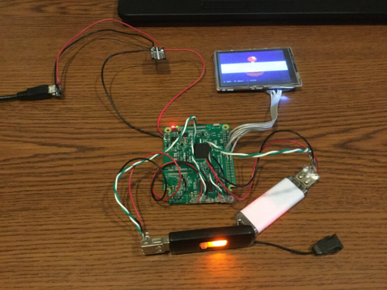
I also tried plugging and unplugging a number of times, and also trying to plug and unplug my USB controller and a drive in and out and things seem to be ok.
$ lsusb -t
/:  Bus 01.Port 1: Dev 1, Class=root_hub, Driver=dwc_otg/1p, 480M
    |__ Port 1: Dev 2, If 0, Class=Hub, Driver=hub/5p, 480M
        |__ Port 1: Dev 3, If 0, Class=Vendor Specific Class, Driver=smsc95xx, 480M
        |__ Port 2: Dev 16, If 0, Class=Mass Storage, Driver=usb-storage, 480M
        |__ Port 4: Dev 15, If 0, Class=Human Interface Device, Driver=usbhid, 1.5M
$ lsusb Bus 001 Device 015: ID 0583:2060 Padix Co., Ltd (Rockfire) Bus 001 Device 016: ID 0781:5406 SanDisk Corp. Cruzer Micro U3 Bus 001 Device 003: ID 0424:ec00 Standard Microsystems Corp. SMSC9512/9514 Fast Ethernet Adapter Bus 001 Device 002: ID 0424:9514 Standard Microsystems Corp. Bus 001 Device 001: ID 1d6b:0002 Linux Foundation 2.0 root hub$ df -h Filesystem Size Used Avail Use% Mounted on /dev/root 7.3G 2.1G 4.9G 31% / devtmpfs 364M 0 364M 0% /dev tmpfs 368M 0 368M 0% /dev/shm tmpfs 368M 5.2M 363M 2% /run tmpfs 5.0M 4.0K 5.0M 1% /run/lock tmpfs 368M 0 368M 0% /sys/fs/cgroup /dev/mmcblk0p1 57M 21M 37M 36% /boot /dev/sda1 2.0G 1.3M 2.0G 1% /media/usb0I'm really glad that it was an issue of the data wires needing to be twisted and not something I fried on the Pi.
While I was trying various things and moving power around I removed the micro USB port for power. I had the same problem as the HDMI port with the surface mount contacts and the through hole pads being too hard to heat up all at the same time. I ended up messing up some more traces down there. I really need to learn a better way to do that, but everything works.
That's enough for today.
Tomorrow I'll do some messing around with the onboard audio to see how crummy it is, or to see if I need to shop for another USB sound card and not crack a capacitor off.
-
@obsidianspider I was going to say try twisting the data lines but you beat me to the punch! I think is so that any interference hits both wires together and kind cancels itself out. Or maybe USB is just magic, and the twisting helps make the magic flow
want to get a tft into your project, look no further than here https://retropie.org.uk/forum/topic/7464/ili9341-tft-screen-guide
-
@moosepr From what I read online it's to reduce/eliminate crosstalk. Kind of like in an Ethernet cable.
-
I broke the spare, old USB sound card I originally intended to use when putting it in my PCB vise last weekend, so this week I ordered a replacement from Amazon. It arrived today, and wow, this thing is small.
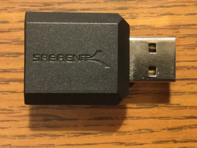
It works well, and sounds better than the old one that it's replacing, so that's good. I'm not sure if the old one caused this, but I noticed an annoying message when launching games:
lvl0: VolumeControl::init() - Failed to find mixer elements!Some googling around leads me to believe that it's a common thing and "that's just the way it is" unless you want to rebuild EmulationStation from source, which I don't.
I saw that the RetroPie wiki had a step that was supposed to address the issue, but it didn't, and frankly, step 5 didn't make sense to me, so I also added the method for enabling USB audio that I found over at sudomod as I think it is clearer and makes more sense to a novice, like me, than the other method that is in the wiki. I'll let the powers that be decide if the "alternate method" should be the preferred one. I still feel like I don't have the authority to make a decision like that.
Now that I know the sound card works, I tried taking the shell off, and it's made really well. Some prying with xacto knives didn't have it budge, so I'm going to see if I can get it apart without breaking it.
-
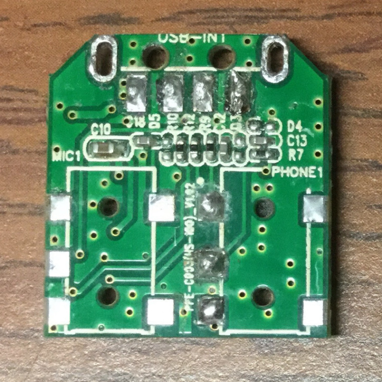
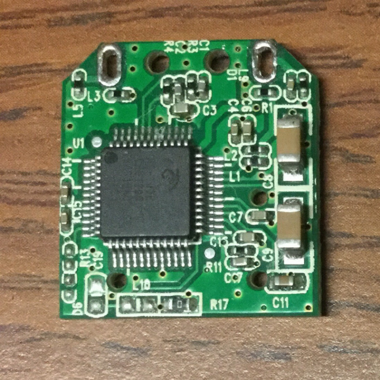
Some repeated scoring with an xacto knife along the seam of the plastic got me inside, and this is a very dense device.
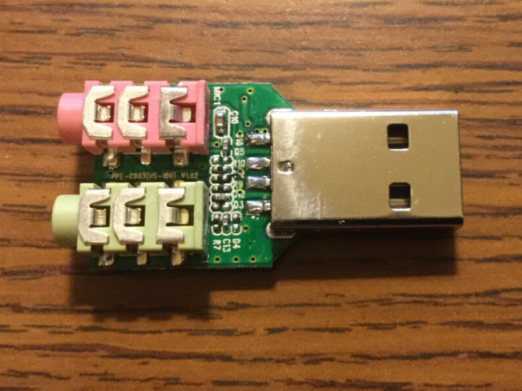
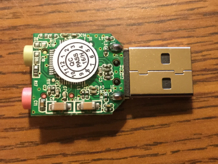
The headphone and microphone jacks are surface mount, which I stink at removing, and the usb plug is surface mount with through hole supports. I mangled the HDMI port and Micro USB on the Pi 3 when I removed those, but on this thing, I can't do that. Not to mention that this is very small, and I'm sure it will load up with heat quickly. I'm not going to attempt to remove anything tonight as it's getting late and I don't want to mess it up. If anyone has any tips for desoldering that USB port, or for removing the headphone and mic jack without heat soaking the whole board and messing something up, please chime in.
I made sure to test the board with the shell off before trying to remove things, and a few rounds of Zed Blade for this week's MAME ROW had me confident that it's working as it should.
-
@obsidianspider yeah those headphone Jack's look a bit tricky. Can you even fit a soldering iron between them?
I would be tempted to get the cutting disk on the dremmel and slice the Jack's down the middle. That should let you then unsolder the outer pins, then remove the plastic, then the inner pins maybe?
want to get a tft into your project, look no further than here https://retropie.org.uk/forum/topic/7464/ili9341-tft-screen-guide
-
@moosepr said in Pi in a Gameboy Advance Build - WIP:
@obsidianspider yeah those headphone Jack's look a bit tricky. Can you even fit a soldering iron between them?
Maybe, but not easily, and I'd end up melting plastic all over the tip.
I would be tempted to get the cutting disk on the dremmel and slice the Jack's down the middle. That should let you then unsolder the outer pins, then remove the plastic, then the inner pins maybe?
That sounds like a good strategy since I'm not trying to preserve the jacks. I think the plan will be to try removing the mic jack since I don't intend to ever use that functionality, so if I mess it up it's acceptable. Then I'll plug it into the Pi to test. Then I'll remove the headphone jack, and plug it into the Pi and make sure that it is detected. After that I'll try attaching leads to the headphone jack and connect it up to one of the new headphone plugs I got from China (maybe it's good they came as a 10-pack) and test again. Then if that's working I'll go after the USB plug, and test again.
-
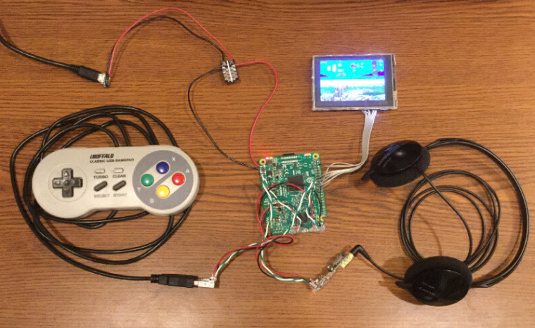
I made some good progress tonight. @moosepr 's suggestion about using a dremel on things before trying to desolder them worked well. Just for a sense of scale, that sound card PCB is about 2cm square.
I managed to connect up the volume wheel and Adafruit amp, and everything works.
For anyone who is also going to try to figure this out with their own build, running
speaker-test -c2at the terminal will cycle white noise back and forth between left and right so you can make sure you have the proper channels identified.When I plug in the headphones, the sound to the speaker shuts off, so that's good, but I am noticing some electrical noise coming from the speaker that is tied to activity on the Pi. (When the green light is flashing on the Pi indicating CPU activity, the buzz changes.) I don't get the buzz from the headphones when plugged in, so I don't think it's coming from the sound card. The buzzing is also present in the speaker even if the audio is only going to the headphones. That leads me to believe that the Adafruit amp isn't filtering anything, or at least if it is, it's minimal, so I'm going to have to see if I can find any information on how to filter the noise and I also want to see how to incorporate the shutdown circuit into triggering when when I plug in the headphones.
-
@obsidianspider yay for destruction! It's lots easier when you can unsolder one pin at a time.
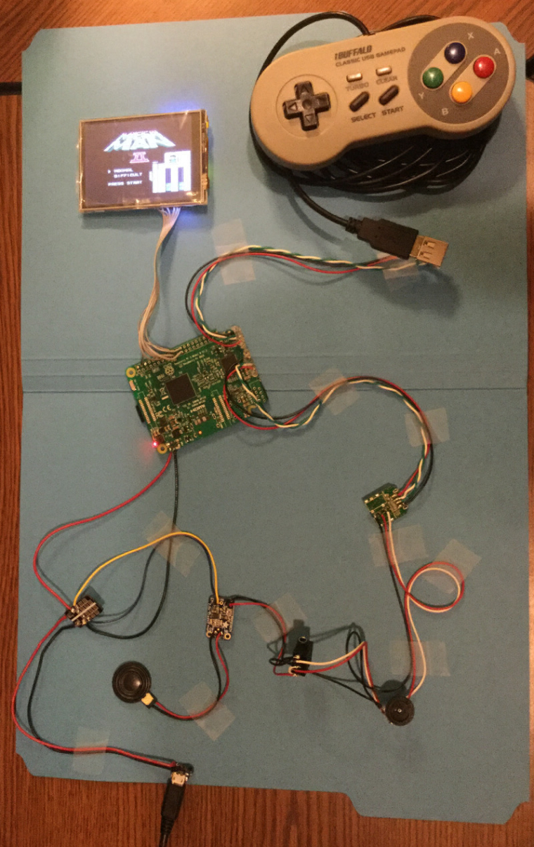
Love the scotch tape setup!
want to get a tft into your project, look no further than here https://retropie.org.uk/forum/topic/7464/ili9341-tft-screen-guide
-
@moosepr the tape was to make it easier to see what was going on in a photo and also to try to isolate audio from power wires due to that buzzing. Some reading is showing that I likely need some ferrite beads and that I should be using some resistors to bridge the stereo to mono, but it's 3:27 AM, so I should probably stop researching and go to sleep.
-
@obsidianspider maybe try powering the amp from a different source, see if that stops and buz?
want to get a tft into your project, look no further than here https://retropie.org.uk/forum/topic/7464/ili9341-tft-screen-guide
-
@obsidianspider
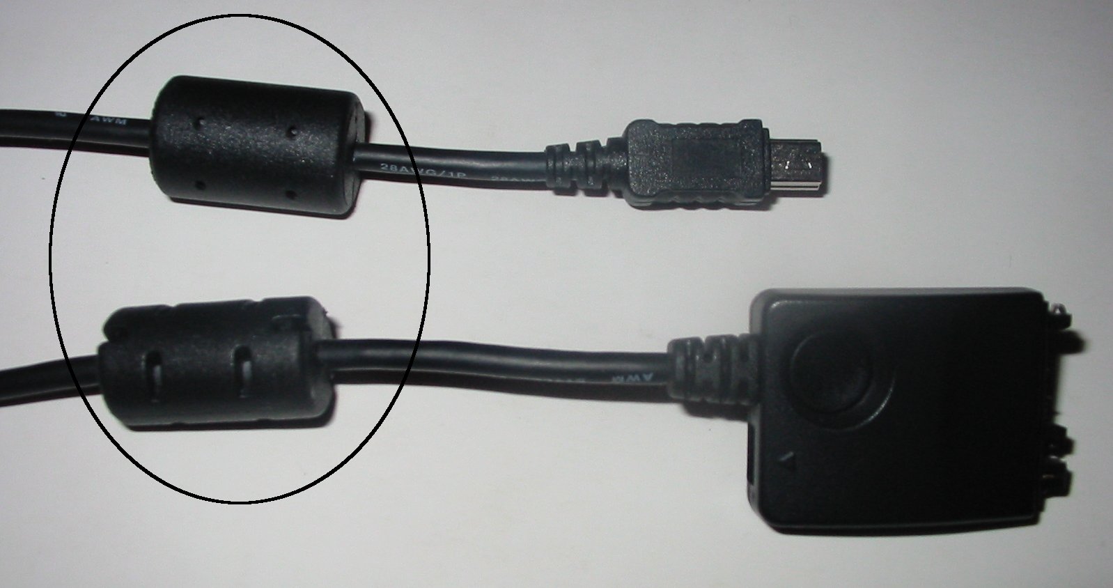
I don't know if this works but I read somewhere that you can edit/boot/config.txtand add the line "disable_audio_dither=1" and this should help with analog audio jack hiss issues. Worth a shot!You might need to put a Ferrite Core on that cable. How it works: "magnetic materials absorb signal interference, reduce signal errors and improve signal integrity"
-
@moosepr That worked, but long term that's not a good solution since I am putting all this in a Gameboy case. I did try adding a capacitor to the power side of the amp, but that had no effect. I may need a specific size, I dunno.
I saw somewhere (I forget where now) that connecting
A-toGNDwould help with the hiss, and it did tremendously. It's not perfect, but WAY better. I also haven't gotten to RadioShack yet to get some resistors for the bridging to mono yet.@backstander I am definitely thinking that I'm going to need some ferrite beads at least, as they're showing up all over on sudomod. The trouble is that no one locally has them, so I'll have to order them online.
I tried the audio dither thing, but since the input source for sound to the amp is from the USB sound card that didn't help.
Off to RadioShack to buy some resistors!
-
@obsidianspider it does sound like is picking up the interference through the power then. Maybe wrapping the power lines round a ferrite ring like @backstander mentioned will help? Do you have any old motherboards or anything knocking about? You can sometimes strike gold with the little copper inducters

-
Some investigation into using capacitors to clean up electrical noise prompted me to try attaching a 0.1 µF capacitor to the power input of the amp. I can't tell how much it helped, but that combined with the 10-Ohm resistors coming off the headphone jack to bridge the stereo into mono has sound that has a level of hissing that I would say won't bring this project to a halt, but I am going to look into buying some ferrite beads to use on the power input as well as the speaker output to try to help clean things up a bit more.
Next up it's a matter of the two things I've been putting off: The power circuit (soft shutdown, low battery warning/shutdown) or modding the case...
-
Why would you need a sound card for a Pi 3? couldn't you just wire into the headphone jack pins and get the sound that way? Or is that not possible? Anyway the project is looking fantastic BTW. =]
-
@thedudester80 It's possible. I initially decided to use USB sound to try to reduce the hiss I was getting when I was doing some testing. The USB soundcard has zero hiss, and for how cheap it was, sounds really great with these old games. Considering that I'm getting some hiss with the Adafruit amp even with the USB soundcard as the source of the audio I'm not sure if it would be better or worse going right off the Pi. It might be worth trying things without the USB soundcard and saving that for my Gameboy Color project. I'll have to think about it.
And thanks for the kind words. This is a whole lot of figuring it out as I go, and I really have no idea what I'm doing.
-
@obsidianspider ooooooh oooooooh oooooh lightbulb moment! Your currently powering the amp from the 5v input to the pi. What happens if you try powering the amp from the usb 5v output? Maybe that is cleaner?
want to get a tft into your project, look no further than here https://retropie.org.uk/forum/topic/7464/ili9341-tft-screen-guide
-
@moosepr it's worth a try. The amp itself is rated to pull up to 800mA at full tilt, it I'm running a tiny speaker and the whole system is only going to be getting 1A from the PowerBoost, so the fact that the USB ports only output 500mA max shouldn't be an issue. I think what I'll try is tagging off the power that's connected to the sound card, at the sound card. Since they'll both be next to each other inside the case that would also cut down on wires in the case if this works. I'll report back, but first, some coffee.
Contributions to the project are always appreciated, so if you would like to support us with a donation you can do so here.
Hosting provided by Mythic-Beasts. See the Hosting Information page for more information.