[SOLVED] Help With 2.2" ILI9341 Display Not Working
-
This article from Adafruit seems helpful, but can anyone confirm my pinout translation? I think I have something hooked up wrong.
-
@obsidianspider the only thing to check is your green cable. It looks to be into gnd rather than pin 25 on the pi side.
Have you enabled the SPI in the raspiconfig?
want to get a tft into your project, look no further than here https://retropie.org.uk/forum/topic/7464/ili9341-tft-screen-guide
-
@obsidianspider also I may have got the command wrong! My memory is failing me
Try this
Sudo modprobe fbtft_device name=adafruit22
-
@moosepr Thanks for the tips. The green wire is hooked up to Pin 25. I'm going to have to check into the SPI configuration. I thought I enabled it, but I've been away for work for the past few days and haven't had a chance to fool with it. Once I get everything working I'll be sure to write it up so future people don't struggle like I am.
-
After installing the dependencies from the Adafruit article and running
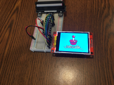
sudo python image.pyI got the screen to light up! But there was no cat image. I tried re-running the command and now I get
pi@retropie:~/Adafruit_Python_ILI9341/examples $ sudo python image.py
Traceback (most recent call last):
  File "image.py", line 41, in <module>
    disp = TFT.ILI9341(DC, rst=RST, spi=SPI.SpiDev(SPI_PORT, SPI_DEVICE, max_speed_hz=64000000))
  File "build/bdist.linux-armv7l/egg/Adafruit_GPIO/SPI.py", line 42, in __init__
IOError: [Errno 2] No such file or directory
It lit up once, so that's a good sign. Now I just need to figure out why that error is showing up and why the cat image didn't display intitially.
Baby steps…
-
@obsidianspider that adafruit bit you found is using python to talk to the screen (which is fine) but im not sure how that would cope with being able to load different images at different times (maybe you could pass the path to the image when calling the python?)
did you try the other command i sent?
Sudo modprobe fbtft_device name=adafruit22
this should make the backlight fire up, then you can type
con2fbmap 1 1
to get your terminal onto the little tft
-
pi@retropie:~ $ sudo modprobe fbtft_device name=adafruit22
doesn't seem to do anythingBut I think I may be on to part of the problem
When I do
ls /dev/*spi*when I'm first booting I get
/dev/spidev0.0 /dev/spidev0.1Which is what Adafruit and some other articles say that I should see if SPI is working
but later (once EmulationStation is fully loaded) I get
pi@retropie:~ $ ls /dev/*spi* /dev/spidev0.1 -
I got it to work… kind of.
The first thing I did was update to RetroPie 4.0.2
But I still think there's something wrong with how I have it connected.
When I boot up the pi, both SPI ports are showing.
pi@retropie:~ $ ls /dev/*spi*
/dev/spidev0.0  /dev/spidev0.1
but when I try to fire up the command from @moosepr the screen doesn't fire up and that first SPI port is gone, and I can't get it back until I reboot
pi@retropie:~ $ sudo modprobe fbtft_device name=adafruit22
pi@retropie:~ $ ls /dev/*spi*
/dev/spidev0.1
After a reboot I have mixed success with the Adafruit Python script.
They have
DC=18andRST=23and when I run theimage.pyfile like that, the display turns on, but nothing displays at all, or it's garbled.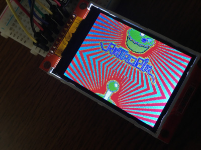
If I change the script to have
DC=24andRST=25to match how I have things wired up, I get the image to display properly.BUT
When I reboot the Pi, if I run the script with the "right" pins selected, the display will never start up in the first place. I have to start it with 18 and 23 and then run it again with 24 and 25. I'm missing something, but at least the darn thing turns on and I can display something
Onward…
-
I got a little script working to display game art based on the game you're playing, failing over to an image for the system if no game art is found, and showing a default image while in EmulationStation, but I still can't get this thing to turn on properly. Here's a video of it working. @moosepr would you be able to tell me what pins on your display you have connected to which pins on your Pi? I'd like to compare with how mine is set up.
-
I wired the backlight pin to 3.3V and now the display lights up properly when the Pi is powered on, and things seem to work with DC on pin 24 and RST on pin 25. It seems like having the backlight on all the time is how these displays are designed to work.
-
It looks like by using the pin 18 initially with the default adafruit script that was sending power to the backlight. I wrote a script to turn on the backlight (and another one to turn it off)
backlighton.pyimport RPi.GPIO as GPIO # Turn on Backlight GPIO.setmode(GPIO.BCM) GPIO.setwarnings(False) GPIO.setup(18,GPIO.OUT) GPIO.output(18,GPIO.HIGH)backlightoff.pyimport RPi.GPIO as GPIO # Turn off Backlight GPIO.setmode(GPIO.BCM) GPIO.setwarnings(False) GPIO.setup(18,GPIO.OUT) GPIO.output(18,GPIO.LOW) -
Huzzah!
I wrote a script to load an image and then turn on the backlight when the Pi Boots up. (I realize that for some of you this is trivial, but right now I feel like some kind of secret ninja wizard. )
I still can't get that whole "
modprobe" thing working, at all, but I'm happy with my progress and for what I want this display to do, I don't know that I need it. -
looking good man!!! the python will be sending the commands direct to the screen, negating the need for the modprobe and a such annoyances
I cant get to my lil device at the moment, its in the loft somewhere buried under a big old pile of stuff, but here is the second best thing


hope this helps
want to get a tft into your project, look no further than here https://retropie.org.uk/forum/topic/7464/ili9341-tft-screen-guide
-
@moosepr That does help! Thanks! This has been quite an educational experience.
Contributions to the project are always appreciated, so if you would like to support us with a donation you can do so here.
Hosting provided by Mythic-Beasts. See the Hosting Information page for more information.