• Recent
  • Tags
  • Popular
  • Home
  • Docs
  • Register
  • Login
RetroPie forum home
  • Recent
  • Tags
  • Popular
  • Home
  • Docs
  • Register
  • Login

Mausberry Shutdown Circuit NES Build Help?

Scheduled Pinned Locked Moved Projects and Themes
power offnes
56 Posts 19 Posters 31.7k Views
Loading More Posts
  • Oldest to Newest
  • Newest to Oldest
  • Most Votes
Reply
  • Reply as topic
Log in to reply
This topic has been deleted. Only users with topic management privileges can see it.
  • Q
    qwaven
    last edited by qwaven 13 Sept 2016, 06:26

    Hi all,

    Wondering if anyone else has wired one of these shutdown circuits to their PI/NES?

    If so perhaps you can help advise which wiring diagram I should be looking at...

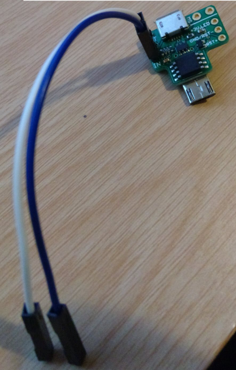
    I have one of these (direct plug micro usb one)
    http://mausberry-circuits.myshopify.com/products/shutdown-circuit-use-your-own-switch

    and I'm hoping to setup to work with my NES.

    However I've seen this diagram on the manufactures site:

    http://mausberrycircuits.com/pages/soldering-your-own-switch

    However every project I've seen online for wiring a pi with a shutdown switch in a NES seems to follow this diagram:

    0_1473747654125_PiWiring.jpg

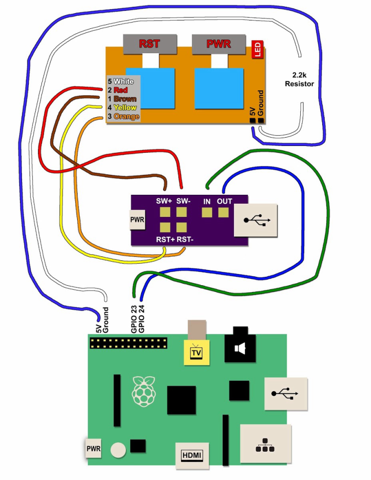
    The only difference being how the LED is wired from what I can tell. Sooo does anyone have any thoughts? It seems a lot easier to use the manufactures diagram but would like to get some confirmation before I actually do...

    Cheers!

    M 1 Reply Last reply 13 Sept 2016, 07:25 Reply Quote 0
    • M
      monstermadeofman
      last edited by 13 Sept 2016, 07:23

      I'm not quite sure why you need to wire the 5V and Ground to the GPIO considering the Mausberry Circuit is what will supply the power and the ground for the power switches anyway. I've not wired up and NES switch to a Mausberry but I have got the same board you have, and I have used it to wire up a power and reset switch.

      I'd go with the manufacturers in most cases especially when they know what people are using them for and took the time to work it out for you.

      Not all those who wander are lost

      1 Reply Last reply Reply Quote 0
      • M
        markyh444 @qwaven
        last edited by 13 Sept 2016, 07:25

        @qwaven I followed that diagram you've posted mate, but with hindsight you probably could use the connection from the mausberry instead.

        Retropie in a NES - Pi 3 with Mausberry circuit shutdown switch wired to buttons and 8bitdo NesPro30 controller
        Retropie in a Saturn Controller - Pi Zero, GPIO controls using DB9 driver
        Retropie in a PSX - Pi3
        https://markyh444.wordpress.com

        1 Reply Last reply Reply Quote 0
        • M
          monstermadeofman
          last edited by 13 Sept 2016, 07:42

          That's also for an older version of the Mausberry board, one that didn't have The LED hole on the board. This is probably better to do it from the board as you don't need the resistor. You just wire the ground to RST-

          Not all those who wander are lost

          O 1 Reply Last reply 13 Sept 2016, 10:39 Reply Quote 0
          • O
            obsidianspider @monstermadeofman
            last edited by 13 Sept 2016, 10:39

            @monstermadeofman said in Mausberry Shutdown Circuit NES Build Help?:

            That's also for an older version of the Mausberry board, one that didn't have The LED hole on the board. This is probably better to do it from the board as you don't need the resistor. You just wire the ground to RST-

            You should always use a resistor when connecting a LED or you'll burn it out prematurely. That said, since the newer Mausberry LED circuit outputs 3.3V you would need to use a different resistor than if you were connecting the LED to 5V.

            📷 @obsidianspider

            1 Reply Last reply Reply Quote 0
            • Q
              qwaven
              last edited by 13 Sept 2016, 17:02

              Hey all,

              Thanks a lot for your input. My initial thought was to use the manufactures diagram. I think that seems like the best choice especially since the other diagram appears to be from an older revision?

              If a different resistor is required would you happen to know what kind? There is no way this would have been already included on the board?

              Cheers!

              1 Reply Last reply Reply Quote 0
              • J
                jsawhite
                last edited by 14 Sept 2016, 02:03

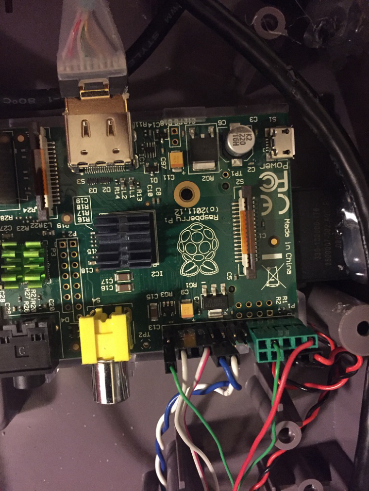
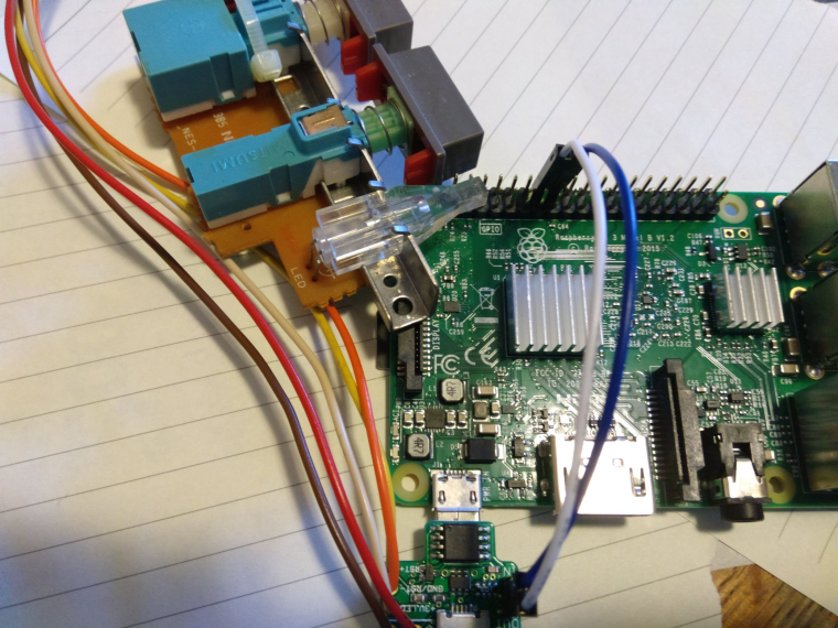
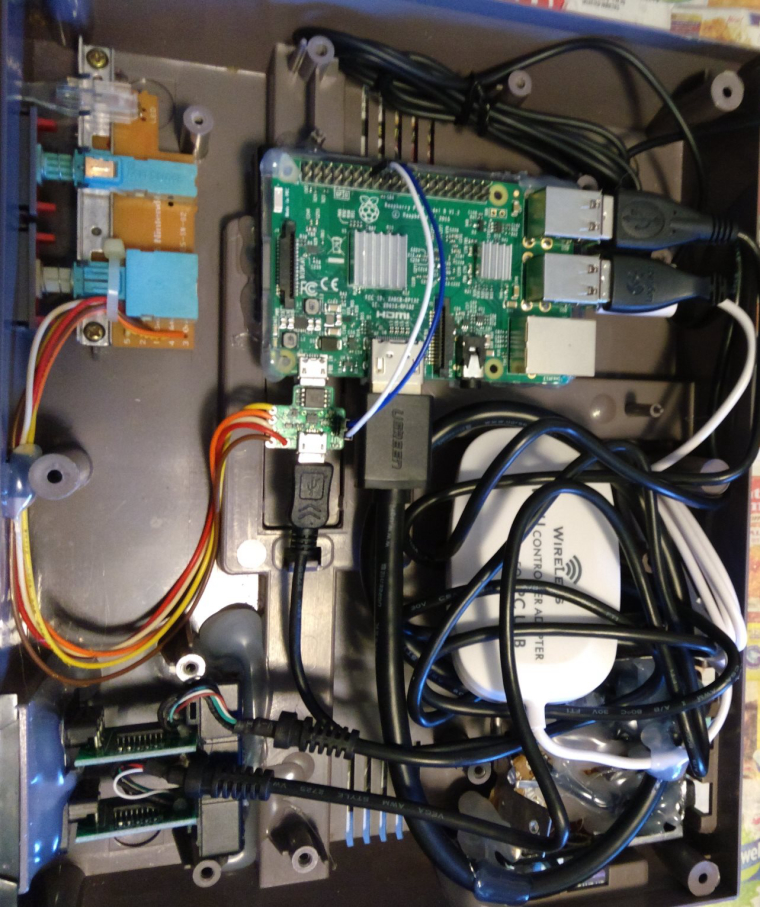
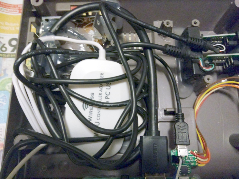
                Here you go... From my NES conversion with the Mausberry controller... The only thing I had to do was to desolder the LED and reverse it's polarity (install it the other way)...

                2_1473818617835_20160914_015647260_iOS.jpg 1_1473818617835_20160914_015641197_iOS.jpg 0_1473818617830_20160914_015634817_iOS.jpg

                1 Reply Last reply Reply Quote 0
                • J
                  jsawhite
                  last edited by 14 Sept 2016, 02:06

                  oh, and pay no attention to the 2 brown wires attached to the bottom of the mauseberry. Those are used for ground connections for the NES controllers (connected to GPIO and using gamecon driver)

                  Q 1 Reply Last reply 14 Sept 2016, 05:48 Reply Quote 0
                  • Q
                    qwaven @jsawhite
                    last edited by 14 Sept 2016, 05:48

                    @jsawhite said in Mausberry Shutdown Circuit NES Build Help?:

                    oh, and pay no attention to the 2 brown wires attached to the bottom of the mauseberry. Those are used for ground connections for the NES controllers (connected to GPIO and using gamecon driver)

                    Hey Jsawhite thanks for the pics. I see a lot more wires in your PI. Are these all required for your switch setup?

                    My switch looks a lot different than yours so still kinda unsure. :)
                    0_1473831207208_microusb.jpg

                    I'm pretty sure I get where each wire goes from the NES buttons based on the manufacture diagram, however do I still require said resister, and if so which one? This is basically what I'm picturing...
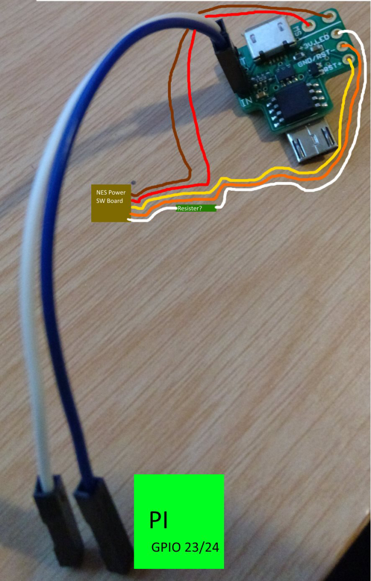
                    0_1473832013805_microusb2.jpg

                    Cheers!

                    1 Reply Last reply Reply Quote 0
                    • J
                      jsawhite
                      last edited by 14 Sept 2016, 09:57

                      Sorry, the extra wires going to the pi are for the NES controllers (I directly connected them to the GPIO). Yes, Mauseberry sells 3 or 4 different variants of the switch, so the boards have a bit different layout. Functions are still the same. No resistor is necessary for this setup. All you have to do is to reverse the polarity of the LED and you're done... :)

                      oh.... wait... you know what. I think I may have cut a trace on the board... let me pull it back apart this evening and I'll update... Hang tight.

                      1 Reply Last reply Reply Quote 0
                      • J
                        jsawhite
                        last edited by 14 Sept 2016, 10:10

                        eh... had a few more minutes this morning, before work and pulled it apart again...

                        No traces cut on the button board! :) So easy connections (and a LED mod). The way you have the wires drawn should work fine.

                        Q 1 Reply Last reply 14 Sept 2016, 19:06 Reply Quote 0
                        • Q
                          qwaven @jsawhite
                          last edited by 14 Sept 2016, 19:06

                          @jsawhite said in Mausberry Shutdown Circuit NES Build Help?:

                          eh... had a few more minutes this morning, before work and pulled it apart again...

                          No traces cut on the button board! :) So easy connections (and a LED mod). The way you have the wires drawn should work fine.

                          Hey Jsawhite,

                          Thanks for your help.

                          So I've gone ahead and connected everything based on what I had drawn. Installed the correct GPIO mappings on the PI...etc.

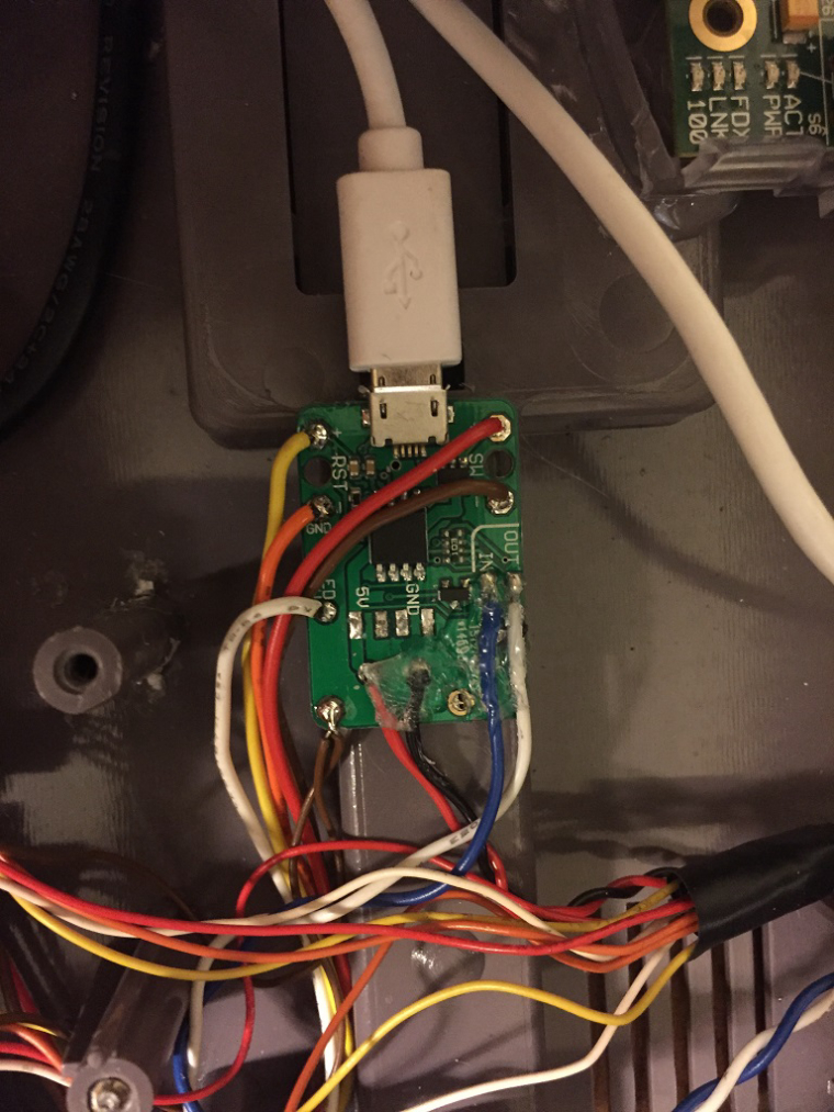
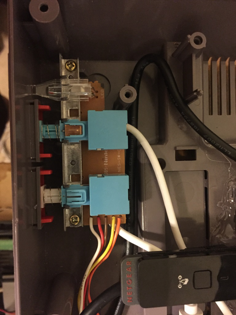
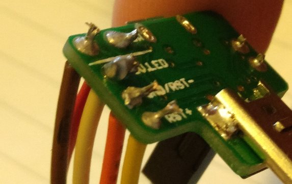
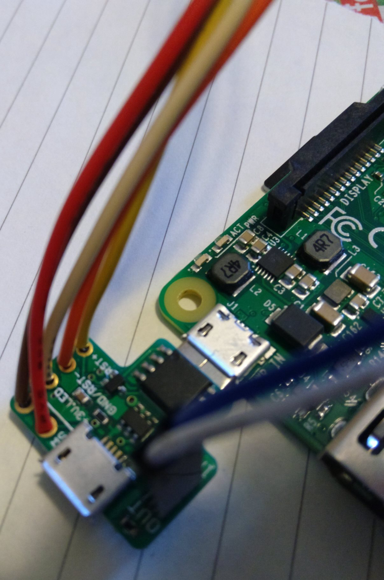
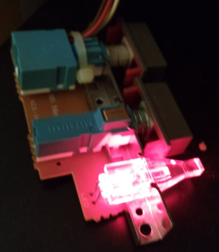
                          The power switch (and restart) seem to be working great! However the LED does not appear to come on at all. Would you (or anyone) have any ideas? I'm hoping this is a user error and its not a faulty LED. :) I've attached some shots of what I've done below. They didn't all come out as clear as I had envisioned but I'm sure they will do.

                          2_1473879951193_wiring03.jpg 1_1473879951193_wiring02.jpg 0_1473879951193_wiring01.jpg

                          Cheers!

                          1 Reply Last reply Reply Quote 0
                          • J
                            jsawhite
                            last edited by 14 Sept 2016, 19:18

                            did you take the led out and reverse it's polarity? You have to desolder the led, flip around 180 degrees and resolder it back in place. The current configuration has the positive lead shared with the reset switch. You need the negative. Just be careful you don't bend the leads too much as they can break off the led.

                            Q 1 Reply Last reply 15 Sept 2016, 05:40 Reply Quote 0
                            • Q
                              qwaven @jsawhite
                              last edited by 15 Sept 2016, 05:40

                              @jsawhite

                              Oops I forgot about doing that!! :)

                              Ok done desolder resolder and now it seems to be working wonderfully. Thanks a bunch!!

                              0_1473917851821_led_working.jpg

                              Now to wait for the rest of my parts and put it all back together. :)

                              Cheers!

                              1 Reply Last reply Reply Quote 1
                              • Q
                                qwaven
                                last edited by 17 Sept 2016, 02:06

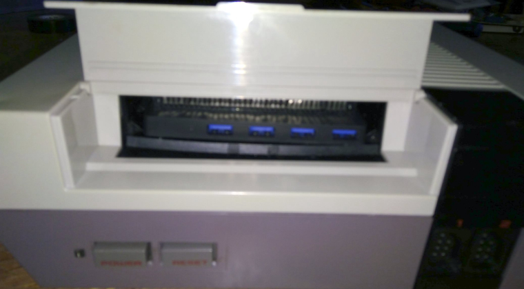
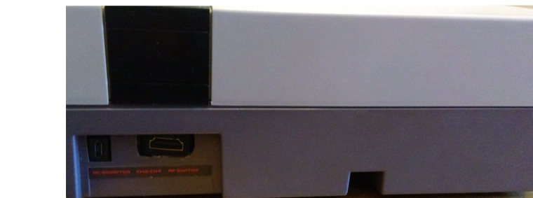
                                Thanks again everyone for your help. In case anyone is interested this is what I've ended up with...

                                -Front "NES" ports are NES-USB adapters
                                -Cartridge bay has a USB hub
                                -LED, POWER and RESET buttons work
                                -HDMI and Power in the back
                                -Wii-U and bluetooth controller capable
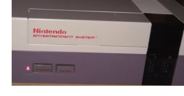
                                0_1474077924557_NES-01.jpg

                                0_1474077932369_NES-02.jpg

                                0_1474077941141_NES-03.jpg

                                0_1474077958695_NES-04.jpg

                                0_1474077968558_NES-05.jpg

                                Cheers!

                                1 Reply Last reply Reply Quote 1
                                • E
                                  elia27
                                  last edited by 17 Sept 2016, 15:08

                                  hi qwaven can you tell me what tipe of usb adapter did you use and if you use any tipe of driver

                                  Q 1 Reply Last reply 19 Sept 2016, 12:55 Reply Quote 0
                                  • Q
                                    qwaven @elia27
                                    last edited by qwaven 19 Sept 2016, 12:55

                                    @elia27

                                    Hi Elia,

                                    Do you mean for the USB hub? The hub is an Anker Ultra Slim 4-Port USB 3.0 Data Hub and no there are no drivers required.

                                    Cheers!

                                    1 Reply Last reply Reply Quote 0
                                    • E
                                      elia27
                                      last edited by 19 Sept 2016, 13:11

                                      hi, no i mean the nes usb adapter, because i bought this https://www.amazon.com/gp/product/B004L5KHKS/ref=oh_aui_detailpage_o03_s00?ie=UTF8&psc=1

                                      and did not work on retro pie

                                      Q 1 Reply Last reply 19 Sept 2016, 14:18 Reply Quote 0
                                      • Q
                                        qwaven @elia27
                                        last edited by qwaven 19 Sept 2016, 14:18

                                        @elia27

                                        Oh I used Basicest BAS1660 NES to PC USB Retro Converter Adapter for PC and MAC

                                        https://www.amazon.com/Basicest-BAS1660-Retro-Converter-Adapter-Cable/dp/B014R069AI/

                                        I believe there are drivers that came with it for PC...etc but I never installed for the PI. Are you using the latest Retropie/PI v3? If not you may want to try that first.

                                        Cheers!

                                        1 Reply Last reply Reply Quote 0
                                        • E
                                          elia27
                                          last edited by 19 Sept 2016, 18:37

                                          @qwaven yes i have tried everithing, thank man

                                          Q 1 Reply Last reply 19 Sept 2016, 21:40 Reply Quote 0
                                          20 out of 56
                                          • First post
                                            20/56
                                            Last post

                                          Contributions to the project are always appreciated, so if you would like to support us with a donation you can do so here.

                                          Hosting provided by Mythic-Beasts. See the Hosting Information page for more information.

                                            This community forum collects and processes your personal information.
                                            consent.not_received