activer bouton arcade gpio
-
@Lolonois
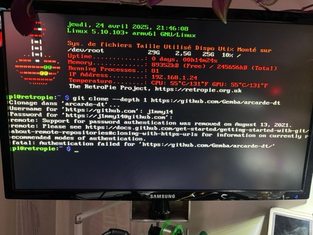
First problem, I started the whole installation from scratch so as not to be bothered by any changes I had made before, but now I can't even perform the first command line. I created an account on the site, but it still doesn't work. When I first installed Arcade DT, I didn't need to create an account. -
-
@Jimmy14 You mis-spelled the repository URL, the final part is arcade-dt and not arcarde-dt.
-
@mitu
😅 -
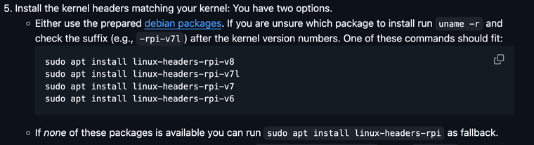
I installed the arcade-dt package again, when installing the kernel headers the first option with the 4 lines did not work so I installed with the second option.
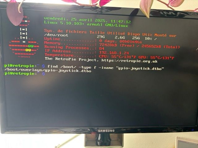
The rest of the installation is well passed I think and after verification I have the gpio-joystick.dtbo file in the boot/overlays folder.
In the boot/config.txt file I copied the following configuration:
use one joystick with 13 buttons
Dtoverlay=gpio-joystick,joy1,joy1-hotkey
I connected a button to the gpio port that corresponds to the A button to test proper operation but nothing happens.
I don't know if I forgot to do something or if I got the wrong place.
And is it possible to connect the buttons of player 2 only or it is mandatory to connect the buttons of player 1?
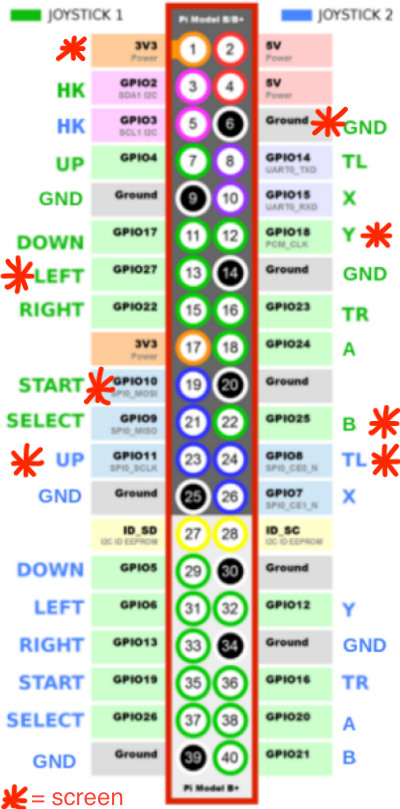
I ask for it because I have a 1.69 inch tft screen connected to the gpio port (it is not active for the moment) and the screen uses 4 gpio port identical to the player 1 connection while if I can use player 2 there are only 2 buttons that are also used by the screen and I would have to be able to change the connection of these two gpio ports to another gpio port so that it is no longer connected in the same place as the screen.
I don't know if I'm clear in my explanation.
-
-
in English ;)
-
Thanks for the verbose input.
Let's reduce complexity of your setup a bit.
First: Can you assure that no overlay ("driver") is loaded for the TFT screen in the
config.txt. I guess you know what to disable (#) in theconfig.txtto start without the TFT screen and with HDMI only for the moment. Also remove any wire from the TFT to the GPIO.Second: You don't have to wire anything for the Joysticks at the moment. Let's start with one Joystick (
joy1and hotkey if you want).After the TFT is disabled in the config.txt and one Joystick is enabled: Reboot and run this command
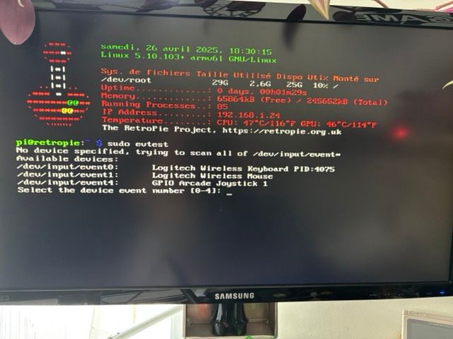
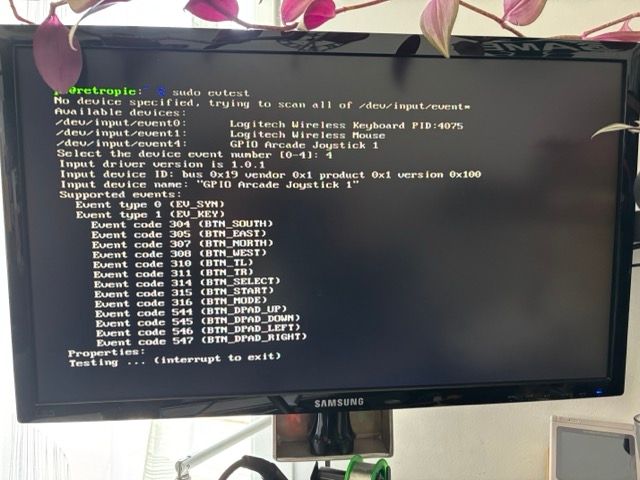
sudo evtest. You should get an output like (one Joystick with HotkeyBTN_MODEin the example below):$ sudo evtest No device specified, trying to scan all of /dev/input/event* Available devices: /dev/input/event0: GPIO Arcade Joystick 1 Select the device event number [0-0]: 0 Input driver version is 1.0.1 Input device ID: bus 0x19 vendor 0x1 product 0x1 version 0x100 Input device name: "GPIO Arcade Joystick 1" Supported events: Event type 0 (EV_SYN) Event type 1 (EV_KEY) Event code 304 (BTN_SOUTH) Event code 305 (BTN_EAST) Event code 307 (BTN_NORTH) Event code 308 (BTN_WEST) Event code 310 (BTN_TL) Event code 311 (BTN_TR) Event code 314 (BTN_SELECT) Event code 315 (BTN_START) Event code 316 (BTN_MODE) Event code 544 (BTN_DPAD_UP) Event code 545 (BTN_DPAD_DOWN) Event code 546 (BTN_DPAD_LEFT) Event code 547 (BTN_DPAD_RIGHT) Properties: [...]You may get presented more event devices, pick the number which relates to "GPIO Arcade Joystick 1".
Do you get this output? -
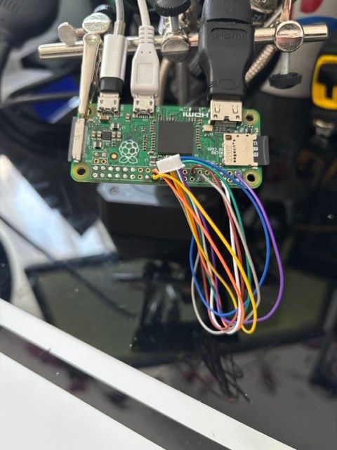
Yes, I assure you that no driver is loaded in the config.txt file for the TFT display. It's not even connected to the socket; only the wires are soldered to the Raspberry Pi Zero's GPIO.
Here are the results:
-
Great. The output means software side is working as expected.
Now, if you let
sudo evtestrunning and then connect a button or GPIO pin to Ground (GND) you should get a signal fromevteston the screen. Any button is low active (i.e. when the voltage level is 0 it means a button is pressed). When a button is unpressed (open) the voltage is 3.3V. -
@Lolonois
It's good, it works in player 1, but how do I modify the button input GPIOs so that they are no longer on the same GPIOs used by the TFT screen? -
I noticed a small error (I would even say that it is an incisive detail) but I connected the A player 1 button and it is the B player 1 button which is detected, is this normal or a problem coming from my configuration?
-
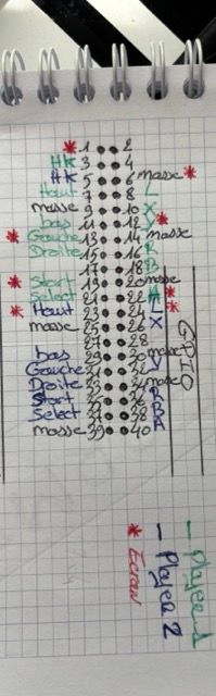
As I explained above, I'm using a TFT screen connected to GPIO in this configuration.
The problem is that the GPIO connections for Player 1's buttons are identical to four GPIO connections on my screen, and for Player 2, there are two GPIO connections identical to those on the screen. (See diagram above.) -
@Jimmy14 said in activer bouton arcade gpio:
I connected the A player 1 button and it is the B player 1 button which is detected, is this normal or a problem coming from my configuration
This is not specific to your configuration. The assignment could be flipped in the
*.dtssource files (or in RetroArch in upper software layer), but don't go that way (yet) - see my next answer on your next post. -
@Jimmy14 said in activer bouton arcade gpio:
As I explained above, I'm using a TFT screen connected to GPIO in this configuration.
That is what we will handle now.
Apologies, if I took the long road, but first I wanted to assure that a simple setup with one joystick works.So, as the TFT display uses pins from both joysticks and you can not dual-use a GPIO pin for two devices, I see two options:
One will take a little more space, the other takes less space but needs more fiddling in the*.dtsfiles.Option 1:
Get two MCP23017 (port expander) on a breakout board, they will use I2C (simple but effective wire protocol) instead of one GPIO port per Button/Direction. Daisy-chain them as I outlined on the Arcade DT project site. The MCP will use the I2C ports of the Raspberry Pi (GPIO2 and GPIO3), which are unused by the TFT. Wire the buttons to the MCP and use the configuration in config.txt instead of thegpio-joystickentry:# two MCP 23017 connected joysticks, the second with: I2C address 0x21, IRQ on GPIO17 dtoverlay=gpio-mcp-joystick,joy1 dtoverlay=gpio-mcp-joystick,joy2,addr=0x21,gpiopin=17This should work as GPIO4 and GPIO17 are not used by the TFT display.
If you wire/solder some MCP pin to the "wrong" BTN function you can change the MCP ports to the BTN function in this file. However any changes there need a recompile/re-install and re-boot.
Option 2:
Use one Joystick directly on GPIO and one via an MCP23017. I would go only this path if space is a absolute premium in your Arcade build.It also requires that you only use spare GPIO ports which are neither used by the TFT (thus not GPIO 18,27,10,11,25,8) nor by the MCP23017 (thus not GPIO 2,3,4).
The GPIO ports for Joystick 1 via GPIO should then be entered in
this brcm,pins line, also altered in fragment@3 in the up, down, left, ... sections that each GPIO from fragment@1 (brcm,pins) is used exactly once.Additionally the Hotkey configuration in fragment@5 and fragment@7 should be adjusted to a spare GPIO (as the currently defined GPIO 2 is needed for I2C and MCP).
Eventually I would remove any even fragment@ (2,4,6,8) entry and anything that relates to joystick2 in
gpio-joystick.dts(as joystick 2 will be addressed via MCP).That said, I guess using two MCP is the easier option.
Hopefully, my answer is not too confusing. If something is not understood please let me know.
-
@Lolonois
Since space is a critical factor for my arcade project (transforming a Nintendo NES controller into a portable game console with a small integrated TFT screen), I'd prefer to use the option where I modify the GPIO ports.
I only need to configure player 1; player 2 is useless.
Without wasting your time, you might not have a gpio-joystick.dts file, or at best, a gpio-joystick.dtbo file that matches my configuration. 😅
I'm not sure I'll be able to properly modify and compile the gpio-joystick.dts file to match my configuration. 🤣
Thanks. -
I deleted the .dtbo files that were created during installation in the arcade-dt and overlays folders, then I modified the gpio-joystick.dts file (see below), then I ran the command:
sudo make install
It created a gpio-joystick.dtbo file in the overlays folder, but when I run the command: evtest, I don't get the gpio arcade joystick 1 option to test the buttons.''' /*
- Device Tree Source for GPIO connected arcade controllers.
- Supports up to two controllers with max 13 buttons each.
- Copyright (c) 2024 Gemba @ GitHub
- SPDX-License-Identifier: GPL-2.0-only
*/
#include <dt-bindings/input/linux-event-codes.h>
#include <dt-bindings/gpio/gpio.h>/dts-v1/;
/plugin/;/ {
compatible = "brcm,bcm2835", "brcm,bcm2712", "brcm,bcm2711", "brcm,bcm2710", "brcm,bcm2709", "brcm,bcm2708";fragment@1 { target = <&gpio>; __dormant__ { button_pins1: button_pins1 { /* joy1: up dn le ri st sl tl x y tr a b */ brcm,pins = < 4 17 6 22 19 9 14 15 12 23 24 21>; /* GPIO port numbers */ brcm,function = <0>; /* all input */ brcm,pull = <2>; /* all pull up */ }; }; }; fragment@2 { target-path = "/"; __dormant__ { gpio-joy1 { compatible = "gpio-keys"; label = "GPIO Arcade Joystick 1"; status = "okay"; pinctrl-names = "default"; pinctrl-0 = <&button_pins1>; /* cf. https://github.com/torvalds/linux/blob/master/include/uapi/linux/input-event-codes.h */ up1: up { linux,code = <BTN_DPAD_UP>; gpios = <&gpio 4 GPIO_ACTIVE_LOW>; label = "BTN_DPAD_UP"; }; down1: down { linux,code = <BTN_DPAD_DOWN>; gpios = <&gpio 17 GPIO_ACTIVE_LOW>; label = "BTN_DPAD_DOWN"; }; left1: left { linux,code = <BTN_DPAD_LEFT>; gpios = <&gpio 6 GPIO_ACTIVE_LOW>; label = "BTN_DPAD_LEFT"; }; right1: right { linux,code = <BTN_DPAD_RIGHT>; gpios = <&gpio 22 GPIO_ACTIVE_LOW>; label = "BTN_DPAD_RIGHT"; }; start1: start { linux,code = <BTN_START>; gpios = <&gpio 19 GPIO_ACTIVE_LOW>; label = "BTN_START"; }; select1: select { linux,code = <BTN_SELECT>; gpios = <&gpio 9 GPIO_ACTIVE_LOW>; label = "BTN_SELECT"; }; tl1: tl { linux,code = <BTN_TL>; gpios = <&gpio 14 GPIO_ACTIVE_LOW>; label = "BTN_TL"; }; x1: x { linux,code = <BTN_X>; /* BTN_NORTH */ gpios = <&gpio 15 GPIO_ACTIVE_LOW>; label = "BTN_X"; }; y1: y { linux,code = <BTN_Y>; /* BTN_WEST */ gpios = <&gpio 12 GPIO_ACTIVE_LOW>; label = "BTN_Y"; }; tr1: tr { linux,code = <BTN_TR>; gpios = <&gpio 23 GPIO_ACTIVE_LOW>; label = "BTN_TR"; }; a1: a { linux,code = <BTN_A>; /* BTN_SOUTH */ gpios = <&gpio 24 GPIO_ACTIVE_LOW>; label = "BTN_A"; }; b1: b { linux,code = <BTN_B>; /* BTN_EAST */ gpios = <&gpio 21 GPIO_ACTIVE_LOW>; label = "BTN_B"; }; }; }; }; fragment@3 { target = <&gpio>; __dormant__ { hotkey_pin1: hotkey_pin1 { brcm,pins = <2>; brcm,function = <0>; brcm,pull = <2>; }; }; }; fragment@4 { target-path = "/"; __dormant__ { gpio-joy1 { compatible = "gpio-keys"; status = "okay"; pinctrl-names = "default"; pinctrl-0 = <&button_pins1>, <&hotkey_pin1>; hk1: hotkey { linux,code = <BTN_MODE>; gpios = <&gpio 2 GPIO_ACTIVE_LOW>; label = "BTN_MODE"; }; }; }; }; __overrides__ { /* odd fragments for joystick 1 */ joy1 = <0>, "+1+3"; joy1-hotkey = <0>, "+5+7"; /* per dtparam overwriteable */ /* joy1 */ up1 = <&button_pins1>, "brcm,pins:0", <&up1>, "gpios:4"; down1 = <&button_pins1>, "brcm,pins:4", <&down1>, "gpios:4"; left1 = <&button_pins1>, "brcm,pins:8", <&left1>, "gpios:4"; right1 = <&button_pins1>, "brcm,pins:12", <&right1>, "gpios:4"; start1 = <&button_pins1>, "brcm,pins:16", <&start1>, "gpios:4"; select1 = <&button_pins1>, "brcm,pins:20", <&select1>, "gpios:4"; tl1 = <&button_pins1>, "brcm,pins:24", <&tl1>, "gpios:4"; x1 = <&button_pins1>, "brcm,pins:28", <&x1>, "gpios:4"; y1 = <&button_pins1>, "brcm,pins:32", <&y1>, "gpios:4"; tr1 = <&button_pins1>, "brcm,pins:36", <&tr1>, "gpios:4"; a1 = <&button_pins1>, "brcm,pins:40", <&a1>, "gpios:4"; b1 = <&button_pins1>, "brcm,pins:44", <&b1>, "gpios:4"; hk1 = <&hotkey_pin1>, "brcm,pins:0", <&hk1>,"gpios:4"; };};
''' -
@Jimmy14 pretty close. I was just about to provide you an example
*.dtsbut I see you did it already by yourself. Chapeau!For your question:
I assume thefragment@NNand the numbers in__overrides__are not aligned in your implementation:These two lines (
joy1,joy1-hotkey) below must match thefragment@NNnumbers in the*.dts:Currently you have:
__overrides__ {
    /* odd fragments for joystick 1 */
    joy1        = <0>, "+1+3";
    joy1-hotkey = <0>, "+5+7";
But it should read as:
__overrides__ {
    joy1        = <0>, "+1+2";  /* fragment@1 and fragment@2 */
    joy1-hotkey = <0>, "+3+4";  /* fragment@3 and fragment@4 */
Which means for the device tree parser: If in
config.txtthejoy1is set then do load fragments one and two, and ifjoy1-hotkeyis set inconfig.txtdo load fragment three and four, which should be defined already in the dts file.If they can't be found they are silently not loaded, unless you have set
dtdebug=1in yourconfig.txtand examine the log withsudo vclog -mafter reboot.Hope this helps.
-
It's okay, it works ☺️ I managed to change the GPIO ports for the keys, which were the same as those on the screen.
Now that I've more or less figured out how it works, I'm going to install arcade-dt on my real Retropie setup and finish assembling my project 😉.
If there's any problems, I'll come back and bother you a bit to figure out what's wrong, otherwise I'll come back and post the final rendering anyway.
Thanks for your help. -
Do you have any ideas on Retropie with a Raspberry Pi Zero on how to get a sound output from the GPIOs? Thanks
Contributions to the project are always appreciated, so if you would like to support us with a donation you can do so here.
Hosting provided by Mythic-Beasts. See the Hosting Information page for more information.