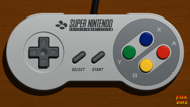
Pi Zero in Gameboy Advance (Based on Super Famicom controller)
-
First time doing something like this, but hopefully it turns out alright.
My idea was to put a Raspberry Pi Zero inside a Gameboy Advance and try to make it look like a Super Famicom controller.

I just ordered a cheap shell from Aliexpress
https://www.aliexpress.com/store/product/Full-Set-classic-Housing-Shell-Case-Cover-Repairt-Parts-for-Nintendo-GBA-Housing-Case-for-Gameboy/1473590_32699495025.html?spm=2114.12010608.0.0.7AOTuH
And then a broken DS from ebay
http://www.ebay.com/itm/122257138751I'm gonna cut the button slots from the DS and use epoxy putty to place it on the gba. I was going to buy colored DS buttons, but I couldn't find all the colors so I'll probably just take the old buttons and paint them. I'm also going to cut the pcb from the DS for the buttons and then wire them to the pi.
My current problem is picking out a display. I was looking at displays sizing from 2.8 inch to 3.5 inch. I'm only going to play retro games up to the snes so I don't need a touch screen, but it seems like there's only touch screens for these sizes. I'm also looking for something that's really cheap, like less than $20.
These are the two that I'm currently looking at:
https://www.amazon.com/BW-3-5-Inch-Monitor-Automobile/dp/B0045IIZKU/ref=lp_10046845011_1_2?srs=10046845011&ie=UTF8&qid=1481326531&sr=8-2
http://www.ebay.com/itm/3-5-TFT-LCD-Touch-Screen-Module-320-x-480-SPI-RGB-Display-For-Raspberry-Pi-B-B-/111987805694?_trksid=p2141725.m3641.l6368
I know the first one is the usual go to Pi display, but I don't know anything about the Pi's wiring. I need to connect both the display and the controls to the Pi and it seems they can sometimes take up the same gpio slots.I haven't looked at anything for batteries, but I wanted to use a rechargeable battery pack that would charge from where the link port would be.

And then two power switches. One for the Pi and display, where the current power switch is, and one for just the display, probably hidden in the cartridge or battery area, to turn off when I want to connect it to a tv.For the volume I probably won't have a speaker, especially if I end up getting the larger 3.5 display, but I'll have a headphone jack and a volume slider or buttons.
Any advice or guides would be helpful.
-
Good luck with your build! I'm trying to do something similar. I found that a 3.2" Sainsmart/Waveshare screen is pretty much the perfect size to fill the opening for the GBA screen, though you do have to modify the board a bit, and it does encroach into the button area. I'd be curious to see how much of a bezel would be needed for a 2.8" screen, and a 3.5" screen would likely require you to completely rework the screen area of the GBA.
-
@Yamt I found that a 2.8 inch ili9341 screen will fit the gap and should let you use the standard glass on the front. I think anything bigger and you need to cut away round the screen, or use some scaling as @obsidianspider has done on his project.
Spi screens use gpio pins from the pi, where as the "reversing camera" ones don't, and leave you with more pins for other uses
I made a little GBA style handheld a while back and strapped it all round a battery. Not a guide, but you can have a look at the thread here
https://retropie.org.uk/forum/topic/2089/yet-another-pi-zero-portableAnd there has been a few GBA style builds like this one
https://retropie.org.uk/forum/topic/960/neopigamerWith the batteries, lithium batteries are the best to go for. They need to be protected from overcharging and over discharge, but they are pretty safe, and come in all shapes and sizes. Just watch for unrealistic capacities
-
@obsidianspider Thanks! I'm hoping that the 2.8 inch screen will fit as closely as the original (I think the actual screen is 2.9 inch) or to hold it in place with some kind of filler between the screen's board and the case.
-
@moosepr The 2.8 inch ili9341 screens are perfect and they're a lot cheaper than the ones I was looking at. I'm surprised they never showed up with a search for just 2.8 inch screens. So thank you for that.
-
So I did some more research on the gpio and from what I understand the BCM pins all do the same thing except for a few which have alternate uses.
So I found a cheap 2.8 inch ili9341 screen and looked up what pins they use.
https://www.aliexpress.com/item/J34-F85-Free-Shipping-2-8-240x320-SPI-TFT-LCD-Serial-Port-Module-PCB-Adapter-Micro/32602444645.html?spm=2114.40010208.4.2.mzAs3eThen I found a post that shows how to set up a controller to gpio, but the pins needed interfere with the screen's pins.
http://sudomod.com/forum/viewtopic.php?t=57So my plan is to hook up the 2.8 inch and set up the controller, but using different BCM pins and that should work. And if it doesn't then I can always set the controller up with a teensy.
-
@Yamt The only thing you need to watch out for with those ili9431 screens is the pcb overhang at the ends. If you measure the distance from the end of the screen to the start of the buttons, you will see what i mean. There are ways round this of course, you can unsolder the pins and use cables to free up some space, also the screen is attached to the PCB with 2 strips of tape. once these are detached, you can actually place the screen and PCB separately (although they are still attached by a ribbon cable). For the final trick, if unsolder the sd card socket, and carefully follow the lines on the PCB, you can actually chop away at least half of the board, making it easier to fit inside the case
Contributions to the project are always appreciated, so if you would like to support us with a donation you can do so here.
Hosting provided by Mythic-Beasts. See the Hosting Information page for more information.