Pi in a Sega Genesis USB Hub Build
-
@obsidianspider are you going for the record for the most builds in 2016? 😛 Good rundown of the build as always!
want to get a tft into your project, look no further than here https://retropie.org.uk/forum/topic/7464/ili9341-tft-screen-guide
-
@moosepr Record? Ha! I still haven't finished one! My Super Famicom is still waiting for a 3D printed panel, and the two Gameboy projects are far from done. I just wanted to make this quickly to have it sit on my desk for MAME ROWs and to be able to take it with me when I travel.
-
@obsidianspider didn't you make another pi hub too? I can't get one project going at the moment!
want to get a tft into your project, look no further than here https://retropie.org.uk/forum/topic/7464/ili9341-tft-screen-guide
-
@moosepr said in Pi in a Sega Genesis USB Hub Build:
@obsidianspider didn't you make another pi hub too? I can't get one project going at the moment!
I had some trouble with the hub for my Gameboy a Advance build. The first one was a cheap fake 2.0 hub that didn't work correctly or at full speed. I got a Targus one that I'm going to be putting inside a GBA game when I get back to that build.
For now I ordered a Mausberry and am on the hunt for a switch with a 4mm throw on it. RadioShack near me literally had NO slide SPST or SPDT switches at all. I have a small SPDT slide switch, but the throw is only 2.5mm, so the Sega power switch wouldn't slide all the way if I used that.
The Mausberry will take a few days to come in, but this weekend I will try to solder the hub to the Pi and mod the case.
-
@obsidianspider do you have the 3d file for the snes back? My roommate has a 3d printer.
-
@obsidianspider this year i have done and competed an intellivision flashback, 2 x nes cartridges, a super nintendo, an atari flasback 1, and my badass apple iie that im about $750 into. Its done but still a few things i want to add to it before i show it off. I am going to do the genesis usb hub but i need to wait until after christmas because i am giving one of the hubs to my roommate for christmas. These things are addictive.
-
@edmaul69 said in Pi in a Sega Genesis USB Hub Build:
These things are addictive.
Absolutely. I went from one Pi2 in early Summer, to that, plus three Pi 3s, four Zeroes, and only one "done" project among all of them (it has nothing to do with RetroPie), and it was a USB hub as @moosepr mentioned. I put a Zero in a USB hub that has an Ethernet port and am using that as a Pi-Hole.
Congratulations on all the projects. I can't wait to see the Apple build.
-
@edmaul69 said in Pi in a Sega Genesis USB Hub Build:
@obsidianspider do you have the 3d file for the snes back? My roommate has a 3d printer.
I don't. My friend was helping design it, then he moved in October and my Super Famicom bottom half of the shell is in a box somewhere. :-/
-
@edmaul69 OK maybe your the winner of the most projects, and probably the most expensive by the sounds of your apple project! I have only made 1! Designed 2 or 3 more, but they all rely on me testing the connectivity on a naked ili9341 screen
want to get a tft into your project, look no further than here https://retropie.org.uk/forum/topic/7464/ili9341-tft-screen-guide
-
Cool idea .... got one USB Hub with all stuff (T-Shirt, Assassins Creed toy and some other thing) from eBay.
I'm in ;) -
@moosepr If those ILI9341 boards you designed work as intended, that will be really helpful for small projects. I am eager to see how your testing works out.
-
@obsidianspider well the plan is, if they work, make a board that you solder the screen on one side, a pi zero on the other, and gpio are round the edges. I need to get the soldering iron out and see if my tiny test boards work
-
@moosepr im sure there must be others out there that have done more than me. But as far as price i might have the most expensive one. I want this to be the best pi i can make it. Putting a 15" flatscreen in the 9" apple iie monitor was the most difficult part of the mod. (Bezel being removed from the monitor makes the monitor big enough for a 15" flatscreen)
-
@edmaul69 we need more posts about this!
-
I got things mostly done this weekend.
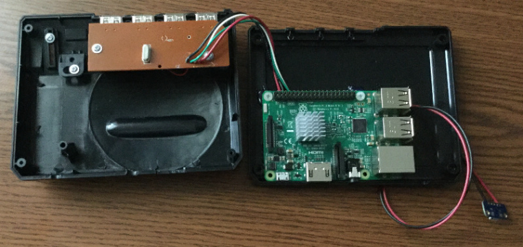
I put the Pi inside the case. I didn't want to mess with trying to desolder the micro USB power port, so I used a Dremel to cut it flush, and I trimmed the pins under the Ethernet port so they didn't stick out too much and then laid it in the case. I did mess up the hole placement a bit so I had to trim the cup for the mounting post on the outside corner as well as the cup for the USB cable strain relief, but it wasn't bad. I also trimmed the ribs on the inside of the top of the case so the HDMI and composite jacks wouldn't interfere, but it was a very easy job.
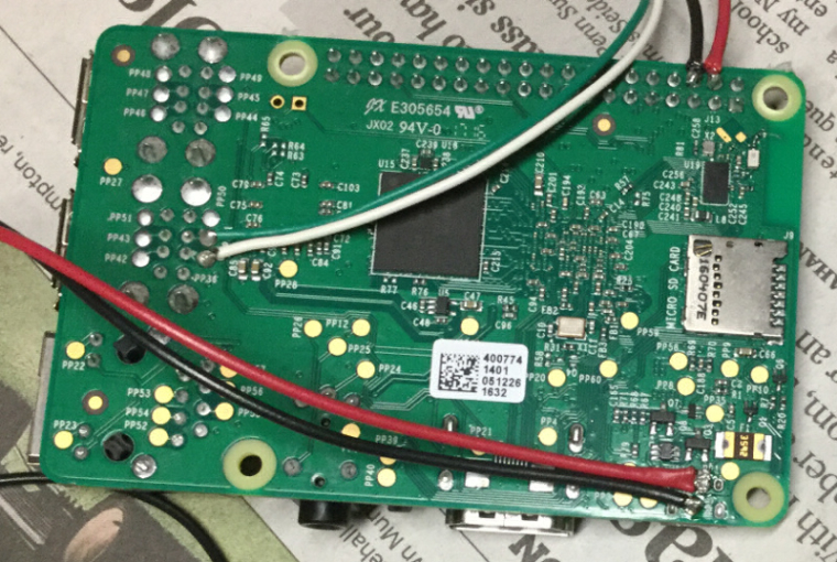
I soldered 22 AWG wire to the test pads under the micro USB port to power the Pi and then decided to power the hub from the 5V and Ground from GPIO using 22 AWG wire so it wouldn't have any current restrictions, just in case I want to plug in something that needs some more oomph. I just tied the data lines into the test pads of one of the USB ports using 28 AWG wire. If I really want to plug in some internal USB stick for storage or something I probably will be able to, depending on how big the Mausberry ends up being. After soldering things up I applied some blobs of hot glue for strain relief.
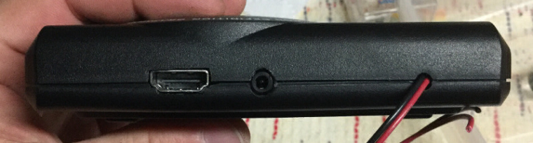
My notching of the back of the case isn't as perfect as I'd like, but you can't exactly put plastic back once you've removed it, so this will have to do. I decided to leave the composite connector on in case I want to connect to an old TV or if I want to plug in speakers.
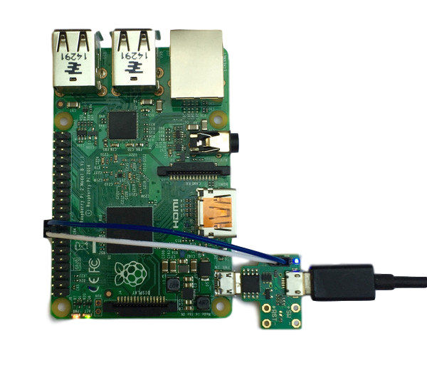
This is the top of the hub before I removed any wires from it. Simple hookup for the power and data lines.

In the interest of cable management I tried running the wires up through the board of the hub from the bottom (there are through holes) but it turned out that when I tried to close the case that things were too crammed in under the hub, so I'm going to have to reroute the wires to the top. I'll work on that once the Mausberry shows up, but the Pi powers up (I temporarily connected the power wires to a micro USB breakout), the heatsink seems to clear, and the hub works, so it's looking promising.
I am having a heck of a time finding a slide switch locally, and I'd really rather not order one from China. I really thought that would be easier to locate. I do have a tiny one, but I want one with a longer action, not the 2mm throw like on the one I have now.
-
Can you make a simple diagram (not crazy technical) or maybe just some better photos explaining your wire layouts? I'm very noobish to all this stuff but want to do the same thing. Like, I'd like to know how you wired the hub to the Pi (what wires go where..). And for power, where exactly are you putting the red/black wires? How are you ultimately going to power it externally.. via a usb charging wall adapter? Do you think I could get a barrel jack and some how come up with a way to hook it up that way? I don't want to have a permanently attached cable hanging out the back if I can avoid it.
Also, is there clearance enough inside the case for the Pi without removing any of the USB/LAN plugs or the GPIO pins? I was afraid I'd have to get a Pi Zero without all that stuff based on other project photos.
I have my Hub ordered, just waiting on delivery.
-
@hansolo77 said in Pi in a Sega Genesis USB Hub Build:
Can you make a simple diagram (not crazy technical) or maybe just some better photos explaining your wire layouts?
Here's a post at sudomod with test pad functions and @ivanretrobit's photo of what USB connections do what. Using both of those was how I figured it out. It seems to work, though I can't confirm it's the "best" way to do it.
For power in (near Micro USB power):
- 5V - PP2
- GND - PP5 (right next to it)
For USB Data
- D- (White Wire) - PP36
- D+ (Green Wire) - PP41 (right next to it)
For USB Power I went to GPIO, but you could also tap into the power for the USB port
- 5V - GPIO 4
- GND - GPIO 6
I'd like to know how you wired the hub to the Pi (what wires go where..)
To connect up to the hub, just note what wire colors went where on the hub and connect the same color wire from the Pi. Leave the LED alone, it will stay connected to the hub as it always was
And for power, where exactly are you putting the red/black wires?
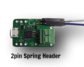
Those will go to the Mausberry that I ordered. I got the use your own switch one with the spring headers.
How are you ultimately going to power it externally.. via a usb charging wall adapter?
The plan is to have the Mausberry against the back of the case with the Micro USB port exposed and then plug it in with a micro USB phone charger like I have always powered the Pi. The phone charger will plug into the Mausberry and the Pi power wires will connect to the Mausberry. The switch (once I find one) will connect to the Mausberry to tell it whether to turn on or off.
Do you think I could get a barrel jack and some how come up with a way to hook it up that way? I don't want to have a permanently attached cable hanging out the back if I can avoid it.
You could if you wanted, but I wanted to stick with Micro USB, and the Mausberry has it already built into the board. When it's done, the Genesis hub won't have any wires dangling out of it. The only reason I have the long power wires on right now is to test it and I'm not sure how things will ultimately be routed with the Mausberry until I get it.
Also, is there clearance enough inside the case for the Pi without removing any of the USB/LAN plugs or the GPIO pins? I was afraid I'd have to get a Pi Zero without all that stuff based on other project photos.
I can close the case just fine without removing anything on the Pi, it's just as you see it above. The photo of the case opening is with the Pi in it, ports and all. The only thing I did was grind the micro USB port flush, because I didn't want to mess things up by trying to desolder it (desoldering SMT stuff is a skill I have yet to become proficient at). I even have a 15mm heatsink that seems to fit fine, but I will confirm once I move the USB wires around. If I have to go with a shorter one, that's fine, but I should be OK. I have a busy afternoon and next few days coming up so that will wait a bit until I have time to mess around more.
I have my Hub ordered, just waiting on delivery.
Let us know how your project turns out! If you have more questions, feel free to ask. I don't claim to know everything, or even a lot, but I am learning a ton and will do what I can to try to help others.
-
Thanks for the feedback. Can I ask what the difference is between the 2pin Spring Header version of the Mausberry is compared to the one I had for my NES?

Is it just a different method of attaching the switch to it? I guess I'm confused because in the picture it shows the pin holes for SW +/- and RST +/- so I don't know what the green box is for.
Who's Scruffy Looking?
-
@obsidianspider i would leave that round hole as a vent hole and place the mauseberry somewhere else. That thing will probably get pretty warm.
-
@hansolo77 The 2 spring header replaces the micro USB that would've plugged into the Pi. What @obsidianspider is doing means this is wired to the power pads rather than using micro USB so it doesn't need that on the Mausberry.
Contributions to the project are always appreciated, so if you would like to support us with a donation you can do so here.
Hosting provided by Mythic-Beasts. See the Hosting Information page for more information.