Pi in a Sega Genesis USB Hub Build
-
@edmaul69 ahhhh because your using the pi 3 yes? I'm using the zero so I should be good with USB you think?
-
@antricluc that would still be an issue. Onece you plug the mausberry into the pi then a cable into that you need to remove the hub to fit it in.
-
Correct. There's not enough room. I have my broken Mausberry that I received (DOA) for my NES build. I fit it in there, but in order to make it work, you need to either plug the other end into the Pi (which would mean having it sticking WAY out the back of the case) or run it via a MicroUSB to MicroUSB cable, which would over clutter the insides of the case. Plus, in order to have the HDMI and Composite flush with the case, you don't really have room to install a cable into the power on the Pi. I suppose if you were going to go that route, you could just cut off the MicroUSB plug (and maybe 2 inches of wire), plug the cable into the Mausberry, then run the wires to the pads on the Pi. But you'd have to cannibalize a cable, and I'd hate to do that. Plus, I don't have a working circuit anyway to experiment with.
-
@cyperghost Did I hear my name? I wish the forum would have notified me that I was mentioned...I could have given some input.
-
@adamspc yes it is about your power on-off circuit.
Can you tell us how it is working and is it possible to lower shipment costs? -
@cyperghost
It works off a momentary switch. Pushing the button will immediately power the board on. It will stay on, so you don't have to hold the button. Holding the button for 3 seconds will power the board off.It has a feature that makes it shut off after the poweroff command is run on the Pi. It does this without any extra software as long as you have the TX pin unused. The third feature is that you can connect to a GPIO pin and use that pin to look for the switch to be pressed, and then issue a shutdown command. The process is explained here.
I'm selling them at a pretty good price considering I'm making them myself. Also, I'm using USPS, and shipping didn't seem to bad to me. They charge around $3 for USA and $8-14 for international. If you guys know of a different shipping company with better prices I don't mind trying someone different.
-
@adamspc Thank you for quick reply :)
A shipment to europa costs about 14$ and if I would take two the value gets to 28$. I think you can send it in a envelope and then the transport costs would lower to 5$ and then I am your man :) -
@cyperghost Yea that was a problem with the shipping calculator on my site. It's fixed now and it combines everything into one package. You can get as many as you want and it will charge $14.
I'm not sure how I feel about using an envelope. I'll see whether the thickness is allowed.
-
@adamspc The price is really hot ... I know you make them on your own and I appreciate your solid work.
-
@cyperghost or if someone over there wants to purchase a bunch of them maybe I can cover some or all of the shipping cost
-
@cyperghost
Also, here is a soldering guide I put together for the board. It give a pretty good overview of the board's function and capabilities. -
@adamspc Oh I see you will also get some I2S amps :) Are these the Adafruit mono amps? These devices are very rare. Maybe I will buy some from you inkl. the soft on-off via company :)
-
OK so I got my Mausberry /w Spring Header circuit today. Soldered it all up, installed the switch scripts, and it's not working exactly right. Need some help...
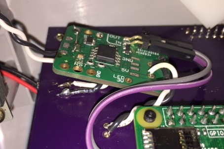
So I have my +5 wire going to PP2 and GND going to PP5. I'm also using the same switch as @obsidianspider. So I have my "edge" pin going SW+ and the "center" pin going to SW-. The IN/OUT wires are setup on their default GPIO pins. Everything wired up, plug it in.. nothing. That's good. Flip the switch, power comes on. That's good. On screen, all of a sudden I'm getting a yellow lightning bolt icon in the top right corner. If I jiggle the wires (maybe I'm just imagining the jiggle is what causes this) the red LED on the Pi blinks. As I said, I might be imagining that, it might blink already because of the lightning bolt. So the system is running ok except for that icon. Then I switch off. The Pi seems to "shutdown", but the circuit doesn't completely cut the power. The red LED on the Pi and the HUB remain on. If I switch on again, nothing happens. I checked with my "direct plug" circuit I have in my NES, and when the switch is off, the system is OFF. The red LED on the Pi is out.
Do I have a bad circuit? Or is there something I'm missing?
Who's Scruffy Looking?
-
@hansolo77 What gauge wire are you using for your power wire? Also, if the Pi doesn't totally shut down, then something is wrong, but first I'd address the lightning bolt issue as that means it's not getting enough power, which can cause all sorts of weirdness and possible file system corruption.
-
@hansolo77 pics too PLEASE! Im sure with my luck I'll end up in the same boat. Doing 3 as gift and don't wanna run into issues so some pics of what you have would be GREATLY appreciated
-
I'm not sure of the gauge. I just grabbed 2 wires off of a jumper wire package I ordered, cut off the ends and soldered them. They're probably not thick enough.
https://www.amazon.com/gp/product/B00GSE2S98/
Maybe it's my crappy soldering skills?


Who's Scruffy Looking?
-
When I've used the spring header flavour I ended up removing it and soldering straight to the board, same with the micro usb, just to save space - works great.
-
@jackal123uk How is it attached though? I looked at the backside of the circuit, and it doesn't look like it's mounted to anything.
-
@hansolo77 this may seem odd to you but take the loop out of your wire. Coiling a wire can cause a lot of issues. Wire thickness looks good. I would remove as many pin headers as possible. Loose pin headers can cause voltage loss as well.
-
Ok, so I took the wires off, cleaned up the solder and resoldered.. same old yellow lightning bolt icon. Then I scrounged around for some better, heavier wire. I found some old sh!tty RCA (red/yellow/white) cables that I don't use anymore. Cut off the ends, trimmed it down, removed the yellow wire, stripped, properly tinned, and then soldered THOSE to the Pi and the circuit. By the way, I figured out how to remove the spring terminals, by just unsoldering the +5 and GND points on the bottom of the circuit (had to google up some images). Now that all of that is out of the way.. SUCCESS!!! The yellow lightning bolt is gone. HOWEVER... :( I still can't get it to completely power off. It's like it goes to sleep rather than cut the power. I'll try taking the loop out, although I'm not sure that will do anything at this point.
FIXED IT!!! I went back and double checked my wiring on the GPIO. I don't know if I had the wires reversed, or maybe on the wrong pins.. but I completely disconnected them and re-connected them. Tried it, and it works now! WHEW! Didn't waste any money, and didn't blow anything up lol.
Is there a way to test all the available aspects of the PI, just so I can have a clear mind in knowing that nothing got messed up while soldering? Like a program or something that goes through and tests all the functions and connections to make sure they're still at factory capability? If not.. somebody should make one so people can test their devices after making modifications.
Anyway... EEEE!!! I'm happy. Now all I have to do is cut off the old hub's tension support post and file out a hole for the new power plug. My only disappointment factor in all this is that I scuffed the crap out of the top of my case (seeing as how I'm working from the bottom). At least these weren't that expensive, maybe I'll buy another one and do it right next time. :)
Contributions to the project are always appreciated, so if you would like to support us with a donation you can do so here.
Hosting provided by Mythic-Beasts. See the Hosting Information page for more information.