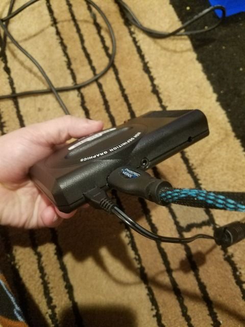
Pi in a Sega Genesis USB Hub Build
-
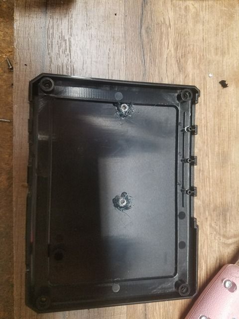
@jackal123uk How is it attached though? I looked at the backside of the circuit, and it doesn't look like it's mounted to anything.
-
@hansolo77 this may seem odd to you but take the loop out of your wire. Coiling a wire can cause a lot of issues. Wire thickness looks good. I would remove as many pin headers as possible. Loose pin headers can cause voltage loss as well.
-
Ok, so I took the wires off, cleaned up the solder and resoldered.. same old yellow lightning bolt icon. Then I scrounged around for some better, heavier wire. I found some old sh!tty RCA (red/yellow/white) cables that I don't use anymore. Cut off the ends, trimmed it down, removed the yellow wire, stripped, properly tinned, and then soldered THOSE to the Pi and the circuit. By the way, I figured out how to remove the spring terminals, by just unsoldering the +5 and GND points on the bottom of the circuit (had to google up some images). Now that all of that is out of the way.. SUCCESS!!! The yellow lightning bolt is gone. HOWEVER... :( I still can't get it to completely power off. It's like it goes to sleep rather than cut the power. I'll try taking the loop out, although I'm not sure that will do anything at this point.
FIXED IT!!! I went back and double checked my wiring on the GPIO. I don't know if I had the wires reversed, or maybe on the wrong pins.. but I completely disconnected them and re-connected them. Tried it, and it works now! WHEW! Didn't waste any money, and didn't blow anything up lol.
Is there a way to test all the available aspects of the PI, just so I can have a clear mind in knowing that nothing got messed up while soldering? Like a program or something that goes through and tests all the functions and connections to make sure they're still at factory capability? If not.. somebody should make one so people can test their devices after making modifications.
Anyway... EEEE!!! I'm happy. Now all I have to do is cut off the old hub's tension support post and file out a hole for the new power plug. My only disappointment factor in all this is that I scuffed the crap out of the top of my case (seeing as how I'm working from the bottom). At least these weren't that expensive, maybe I'll buy another one and do it right next time. :)
-
@hansolo77 Congratulations! I know this had been weighing on you for quite a while. What I did with mine was test all of the USB ports on the hub, make sure I can get in via SSH, run retropie updates, and then I played the darn thing. Also, I see you reworked your power switch into a different orientation. What did you end up doing with that?
As far as scratching the top of the case, what I tried to do was to have paper down, or a piece of cloth when I was working on things. (Except when soldering, I didn't want a firey mess). That seemed to keep the top in decent shape, though there is one spot that is slightly discolored, not sure if it was always like that or if I did it. I didn't really take a good "before" photo where I would be able to tell.
-
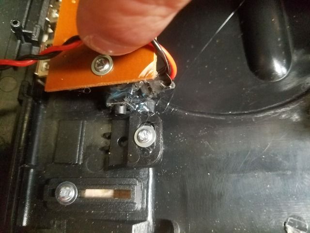
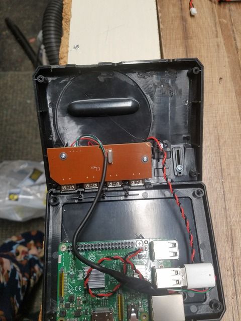
I ended up removing the power switch that it comes with. I just couldn't get the "ordered" switch and the original switch to work right together. So I removed the original switch, and mounted the "ordered" switch in it's place, with the toggle through the hole. Hot glue to mount it. The pins I just sort of bent so they wouldn't cause a clearance issue (probably didn't have to, but it makes me feel better). Mounting the power circuit into the case was a bit of a hassle, since it pretty much levitates in between the 2 halves. What I'm doing to solve that is a bit of a hack job, but it worked. The spring terminal I removed from the Mauseberry circuit is actually pretty darn close height-wise compared to the void left over between the bottom (top) of the case. Last night, I did my best to hot glue the edge of the circuit to the edge of the case, but it wasn't vertically stable. So I hot glued the left-over spring terminal to the case, then hot glued the circuit to the terminal. There's no separating the two now without a razor. But the result is solid, and I can plug in the power cable (with force!) and it doesn't budge. So now my only problem is closing up the case. With the extra thick wires I used for the power, the top (bottom) of the case now won't close right. I'm waiting for some heat sinks, but once I get them and have them installed, I'll probably hot clue the wires down to the back of the Pi. The way they are now, they want to stack on top of each other rather than down flat. Once flat, it looks like there won't be any issues.
-
@hansolo77 Sounds good. Keep us posted!
-
@hansolo77 That's right; it's only the solder to the terminals holding it on. I found that melting the solder with the board upside down was enough for it to quickly and cleanly fall out.
-
Hey everyone, this thread has inspired me to order a Sega Genesis Usb hub and give it a good. I ordered it off shirtpunch for $20 usd the next day I see it on sale for $7.99 :/
As a noob I'm finding it quite difficult to see where each wire needs to go and which parts I need. Can someone please make a guide on which parts exactly are needed and where each wire needs to be soldered on the boards with pictures?
-
@steetsofrage dope ass game by the way. First you wanna be careful prying the hub open. Of the 3 hubs I have they all separated fine with a lil steady pressure. You'll want to pry near the front of the hub where it's being secured by a couple stubs and glue.SOME MAY BREAK, but it should be fine being you will be screwing the two halves together. What pi do you plan on using?What game emulators do you plan to run? Do you plan on the switch powering the unit? Not necessary but deff dope if done correctly.
-
@steetsofrage yeah me and my roommate got lucky and saw the sale so we got 5 extra hubs.
-
@edmaul69 seems every other week they go on sale. Limit 20 per customer
-
It says they're $19.99 for me. :( I want to get a new one now that I have this one working, so I can make one for my brother that hopefully won't get all scuffed.
-
got my hub in and finished today. working reset button too! easy project too!!!!
-
I plan on using a pi 3 and running retro pie, I would also like to use a mausberry to make the switch on the case functional.
-
Good news is shirt punch refunded me $12 USD, keep checking they seem to go on sale often.
-
One thing I ran across when looking at the Mausberry switch page was that it says you can power it via GPIO. Is there a specific reason you chose to use the test pads on the micro USB port instead of running off a 2nd set of 5v/ground pins (pins 2 and 9 or 14) on the GPIO? Just looking at how everything sets up, it looks like it might be a cleaner solution (wire management wise) than the MicroUSB pads. I very well may be missing something that makes it a bad idea :)
@cyperghost might be able to answer that as well?
Huge thank you for documenting your project!
-
@Stig not sure what side of the polyfuse that the solder pads are on but if the are on the usb port side then the pi is protected for overvoltage and stuff. However i have used the gpio many times with no issues at all. For the pi zero if you are using a usb hub some hubs would benefit better if power game from the gpio pins. I split my power between my hubs and my pies. Havent had an issue yet
-
@Stig I never soldered directly to the pads in the build I made. I just used some sockets to restore needed GPIO Pins and therefore I rather would use the GPIO for powering than soldering to the power pads for stability reasons and to exchange/remove power source.
But on the other hand it doesn't matter because you have to solder to the OTG-USB pads to get devices via hub connected.
@edmaul69 There is NO polyfuse in the Raspberry Zero build in!
About power over GPIO
-
@Stig Mainly because I wasn't sure about where the fuse is located and I know that Pi 3s are finicky about power requirements, so going to the test pads seemed "safer"
I'm not sure if it was a better option or not, but it seems to work well in the few weeks I've had the unit together.
-
@cyperghost I guess i never looked and just assumed the pi zero had one. I guess for $5 it wasnt cost effective, plus if it blows up who cares?
Contributions to the project are always appreciated, so if you would like to support us with a donation you can do so here.
Hosting provided by Mythic-Beasts. See the Hosting Information page for more information.