RetroPie forum home
    • Recent
    • Tags
    • Popular
    • Home
    • Docs
    • Register
    • Login
    Please do not post a support request without first reading and following the advice in https://retropie.org.uk/forum/topic/3/read-this-first

    Power On/Off Button is in Reverse... Pushed-IN is OFF and Pushed-OUT is on.

    Scheduled Pinned Locked Moved Help and Support
    raspberry pi 3helpnes classicpower button
    38 Posts 6 Posters 9.5k Views
    Loading More Posts
    • Oldest to Newest
    • Newest to Oldest
    • Most Votes
    Reply
    • Reply as topic
    Log in to reply
    This topic has been deleted. Only users with topic management privileges can see it.
    • AlexMurphyA
      AlexMurphy Banned @briandamico
      last edited by

      @briandamico I doubt anyone is getting tired of helping. You just need to provide more info. BTW, Can you not put images on photob*cket, please. Images can be uploaded to the forum.

      B 1 Reply Last reply Reply Quote 0
      • B
        briandamico @AlexMurphy
        last edited by briandamico

        can u tell me how to do that Alex?
        is that taking the link from PB and inputting it. or is there literally an upload link

        never mind, found it, accept it has an error

        AlexMurphyA 1 Reply Last reply Reply Quote 0
        • B
          briandamico @briandamico
          last edited by

          This post is deleted!
          1 Reply Last reply Reply Quote 0
          • AlexMurphyA
            AlexMurphy Banned @briandamico
            last edited by AlexMurphy

            @briandamico When you hit REPLY there is a wee cloud with an up arrow. I just hate fighting through the adverts on PhotoFuckit.

            1 Reply Last reply Reply Quote 0
            • R
              radiofreero
              last edited by

              That's a 4 prong switch. You will either need to wire it through the connector, use a bread board, or create your own PCB for it. Wiring directly to the button like that will not help.

              B 1 Reply Last reply Reply Quote 0
              • B
                briandamico @radiofreero
                last edited by

                @radiofreero
                the right button is a reset button and the left push button is for power which is what they were originally used for

                now when you say wire it through the connector, what do you mean exactly?

                at this moment its working, just in reverse.

                AlexMurphyA edmaul69E 2 Replies Last reply Reply Quote 0
                • AlexMurphyA
                  AlexMurphy Banned @briandamico
                  last edited by

                  @briandamico If it is working in reverse... Have you tried wiring it in reverse?

                  B 1 Reply Last reply Reply Quote 0
                  • B
                    briandamico @AlexMurphy
                    last edited by

                    @AlexMurphy I've tried every which way and nothing has changed it

                    AlexMurphyA edmaul69E 2 Replies Last reply Reply Quote 0
                    • AlexMurphyA
                      AlexMurphy Banned @briandamico
                      last edited by AlexMurphy

                      @briandamico Ok, I was being facetious, You need, if you want help, to give some basic info, you need to start from the very start. No one can guess your set-up. Please do not post a support request without first reading and following the advice in https://retropie.org.uk/forum/topic/3/read-this-first

                      B 1 Reply Last reply Reply Quote 0
                      • edmaul69E
                        edmaul69 @briandamico
                        last edited by edmaul69

                        @briandamico can you post a link to your switch you bought? So it is probably a dpdt )double pole double throw) or spdt (single pole double throw) switch. You have it wired to normally open (up positition). You need to put it on a different pin set for the normally closed (pushed down)

                        B 1 Reply Last reply Reply Quote 0
                        • edmaul69E
                          edmaul69 @briandamico
                          last edited by

                          @briandamico best way to test is to use a multimeter on the diode setting. ->|- With the button pushed down, find two pins the make the multimeter beep or show something close to 0.00 (zero). Then push it back up. Then if those two pins dont beep pushed up they are the ones you want. The two pins on the opposite side of what you wired to are probably correct pins.

                          B 1 Reply Last reply Reply Quote 0
                          • B
                            briandamico @AlexMurphy
                            last edited by

                            @AlexMurphy well my apologies Alex i was happy with my initial post as I thought it was pretty clear but i am happy to be extremely more in depth. so i will try to do so now

                            Pi Model - Raspberry Pi Model 3 B
                            Power Supply used: NorthPada Raspberry Pi 3 Model B Power Supply Charger AC Adapter 5V 3A PSU Micro USB 5 Feet with Power On / Off Switch
                            RetroPie Version Used - 4.2
                            Built From: Custom from scratch
                            USB Devices connected: 2 soldered USB female connectors
                            Controller used: Custom NES USB and Wii U Wireless
                            Mausberry Shutdown Circuit is being used and is properly set up via script to shut down properly

                            the problem: I have an NES mini (original) that i gut everything but the original Power On/off - reset - LED board.
                            I would like to use the original board and am pretty much am using it for the fact the power push button is in reverse. Out is ON and In is Off. plain and simply

                            I hooked up a sep LED to the Pie via the mausberry shut down LED tab and the ground to the Raspberry pis ground 3 GIO pin.

                            So if if this is too much to figure out, i am open to suggestions and part list suggestions to building a similar Bread board with a push button and reset button and led light if it will work properly. but if we can get the original to work in Non-reverse- id be forever grateful

                            hope this explains everything

                            edmaul69E 1 Reply Last reply Reply Quote 0
                            • edmaul69E
                              edmaul69 @briandamico
                              last edited by

                              @briandamico read my last two posts.

                              1 Reply Last reply Reply Quote 0
                              • B
                                briandamico @edmaul69
                                last edited by

                                @edmaul69 if you go to http://mausberrycircuits.com and click SHUTDOWN CIRCUIT (USE YOUR OWN SWITCH) and see the direct micro USB one thats what i have.

                                now you ask about it being wired normally and i don't know what double pole double throw means and single old double throw means.

                                so how to i change the pin set if i am blunt asking that. I'm sure i already know but you can always tell me again

                                edmaul69E 1 Reply Last reply Reply Quote 0
                                • B
                                  briandamico @edmaul69
                                  last edited by

                                  @edmaul69 ok i can try this with a multimeter
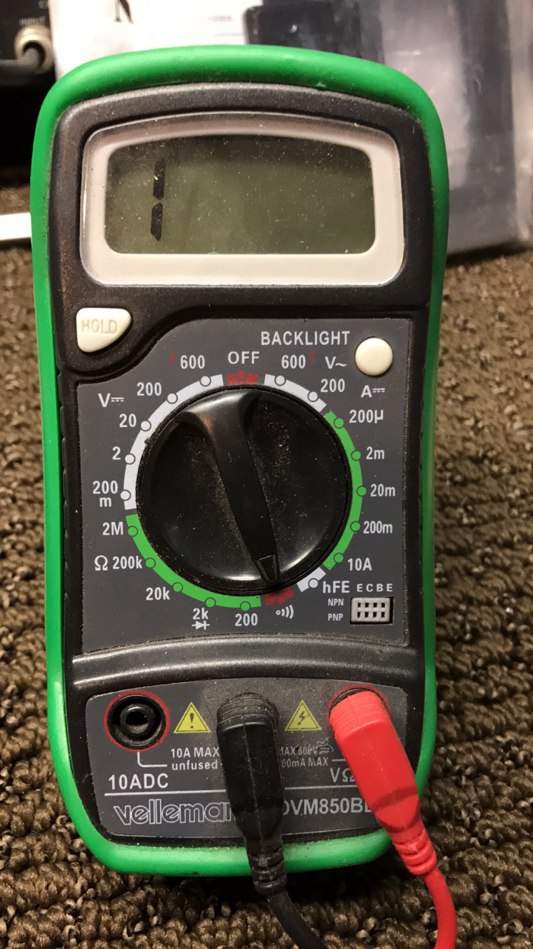
                                  0_1495854761418_IMG_1117.JPG
                                  which you can see here.

                                  what setting would u like me to use

                                  edmaul69E 1 Reply Last reply Reply Quote 0
                                  • edmaul69E
                                    edmaul69 @briandamico
                                    last edited by

                                    @briandamico you see you have two wires soldered to one side of the switch. Move them to the pins on the other side of your switch. That will probably fix it.

                                    B 1 Reply Last reply Reply Quote 0
                                    • B
                                      briandamico @edmaul69
                                      last edited by

                                      @edmaul69 well i did try that and it didn't not change.

                                      i tried many many many many combos with the wires ed.

                                      i did bottom 2 pins left side, bottom 2 pins right side
                                      top right bottom right
                                      top left bottom left

                                      i really did but I'm happy to do the multi meter

                                      1 Reply Last reply Reply Quote 0
                                      • edmaul69E
                                        edmaul69 @briandamico
                                        last edited by edmaul69

                                        @briandamico you need to put your multimeter on the 2k. That is where it shows the diode symbol ->|-. It should beep if you touch your test leads together or show 0.00 ish

                                        B 1 Reply Last reply Reply Quote 0
                                        • B
                                          briandamico @edmaul69
                                          last edited by briandamico

                                          @edmaul69 ok should i desolder the wires i have on the back? or leave them.

                                          and you say when i touch two pins and the button is pushed IN, then i have my ON function and when i push out i should not get a signal?

                                          and should i have the power on for real doing this?

                                          edmaul69E 1 Reply Last reply Reply Quote 0
                                          • edmaul69E
                                            edmaul69 @briandamico
                                            last edited by edmaul69

                                            @briandamico with it set on 2k on your multimeter it should beep or show 0.00 ish when you touch your test leads together. Same if you have the switch pushed down and you find the correct pins. Then when you put the switch in the off position those two pins shouldnt beep when you touch them.

                                            B 1 Reply Last reply Reply Quote 0
                                            • First post
                                              Last post

                                            Contributions to the project are always appreciated, so if you would like to support us with a donation you can do so here.

                                            Hosting provided by Mythic-Beasts. See the Hosting Information page for more information.