What am i doing wrong with my hd44780 16x2 lcd?
-
@cyperghost will do m8, the level shifter came today so I'm gonna wire it up tomorrow if I get time. I'll post pics of the display working but it might be a while for the finished product.
I need a day when my boss isn't in so I can mill the facia.
Thanks for your time aswell m8, it's been much appreciated. You and future.child. -
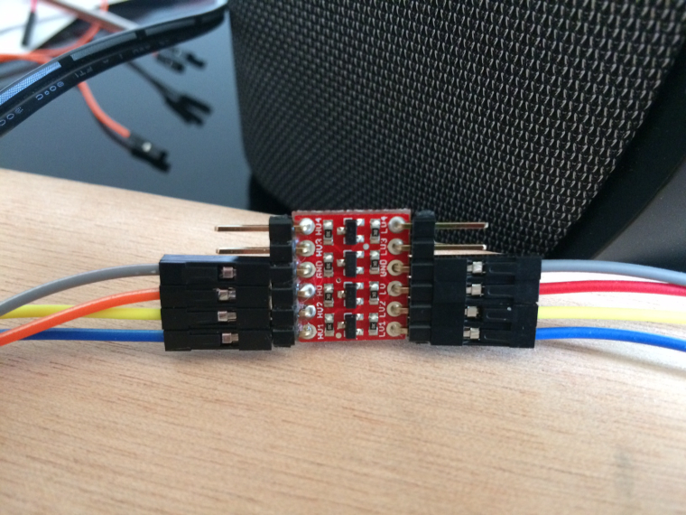
Hi, I'm about to wire up this level shifter but I'm a bit confused on the wiring.
Is this right so far?Level Shifter/ Pi / LCD
LV / pin 1 (LV from level shifter to pin 1 on pi)
LV1 / pin 3 (LV1 from level shifter to pin 3 on pi)
LV2 / pin 5 (LV2 from level shifter to pin 5 on pi)
GND / pin 6 / GND (gnd from level shifter to pin6 on pi, opposite gnd on level
shifter to gnd on LCD?)
HV / pin 2 / VCC (HV from level shifter to pin 2 on pi, then?)
HV1 / SDA (HV1 from level shifter to SDA on i2c?)
HV2 / SCL (HV2 from level shifter to SCL on i2c?) -
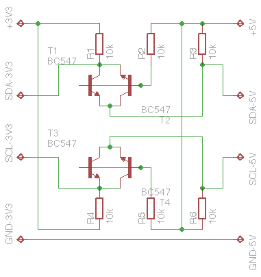
@Boz You are 100% on the right track :)
L means Low
H means HighL1 = 3,3V and is connected to your Pi power Pin 1
H1 = 5,0V and is connected to your Pi power Pin 2
G = Ground connected to your Pi (3,3V and 5,0V and of course also LCD via Levelshifter)LV1 = SDA Pin 3 from your Pi
LV2 = SDL Pin 5 from your PiHV1 = SDA to your I2C LCD
HV2 = SDL to your I2C LCDGND is GND and doesn't matter were you connect to your Pi because voltage potential is equal!
You connect Ground from LCD to your Pi, also the 3,3V and 5,0V are connected to your Pi. You can seepicture in my postingUsually you can connect all grounds together.
But at first try I would use 3,3V/Ground and 5,0V/Ground seperate because they are needed to reference voltage level. -
So I connect the levelshifter GND LV side (3.3v) to pin 6 (GND) on the pi and GND HV side (5v) to say pin 9 (GND) on the pi also? How do I also connect GND from the levelshifter to the lcd with no GND pins left?
(Please bear with me I don't have a brilliant understanding of voltage etc)
ps: I'm using direct wiring and no breadboard. -
@Boz The best way is to connect every ground as single line - you will avoid interferences with that. But you can connect ground 3,3V to Pi ground and connect HV ground to I2C backpack.
But on the other hand (I didn't know you don't have a breakboard):
As they use all the some potential it isn't needed to wire every ground to annother point.
Here you see the shematics
I used one of my old B+ and used a Pi Dish but not for 25$ :))
-
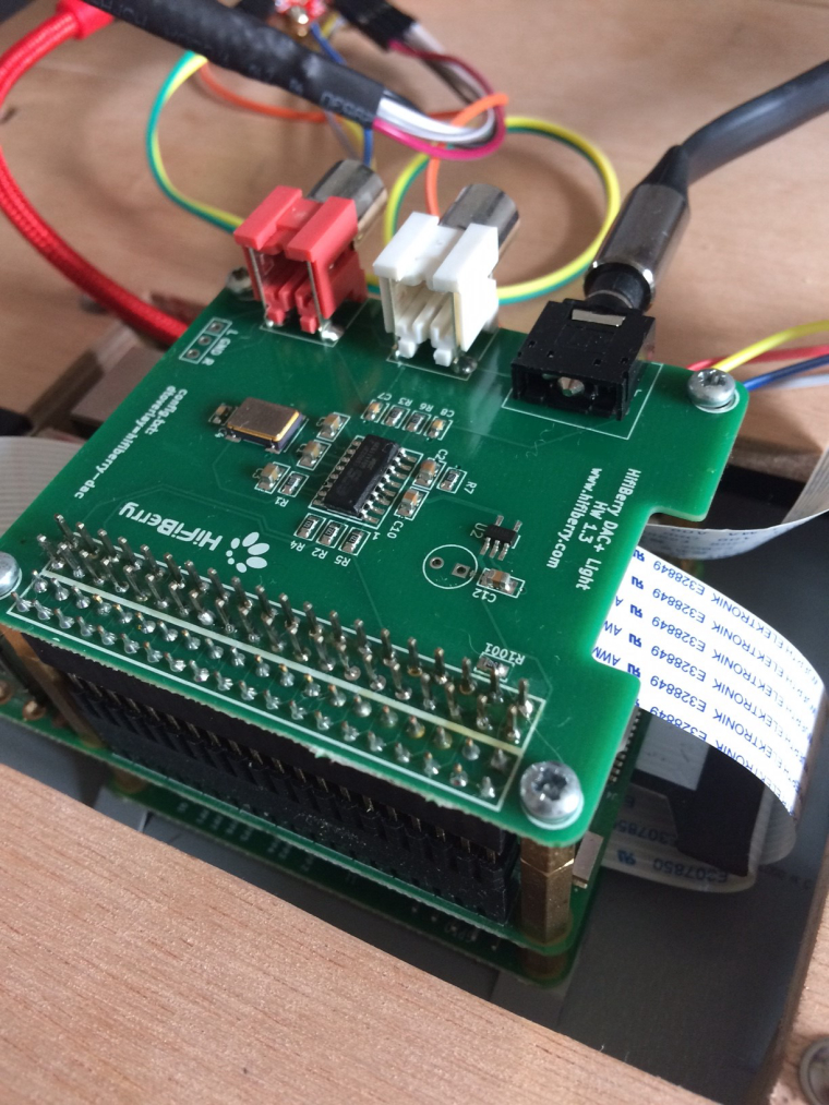
I must have messed up somewhere there's no power to the lcd.
I have the wires connected as you said (will double check again in a min) but connected via the header on my dac.
I notice I didn't connect any wire to the vcc on the i2c backpack is this correct? -
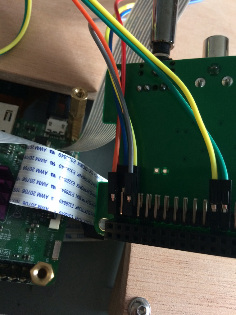
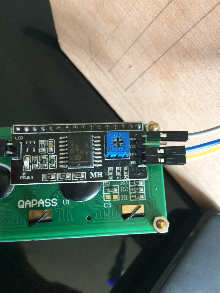
Here's some pics:
-
I have it wired like so:
LV (red) to pin1 on dac
HV (orange) to pin2 on dac
GND (grey) to pin6 on dac
GND (grey) to GND on i2c
LV1 (blue) to pin3 on dac
LV2 (yellow) to pin 5 on dac
HV1 (blue) to SDA on i2c
HV2 (yellow) to SDL on i2cNothing connected to VCC on i2c.
-
Can you measure voltage on HV? That has to be 5,0V
Then connect HV also to VCC on your I2C LCD - with 5,0VThe connection HV and LV on level shifter is only for internal comparism 3,3V and 5V it is not intended as supply. The LCD must glow if the there is 5,0V...
The Pi got annothe 5V pin... Pin2! Use that for LCD connect!EDIT: Sorry Pin 2 is already used... Can you expand it? Or what about Pin 4? You need 5V for the LCD!
-
Ok so I just add a wire from pin 4 on pi(dac) to vcc on i2c and leave the rest?
I thought the idea was to not directly connect 5v power to the i2c backpack ?
-
Yes
But I'm not sure if the device can be detected. I2C is multibus so it should work.... but we will see. Maybe I2C adresses from your devices are the same. Just connect and report!
Your have a seconds Pi.... maybe you can get it on this to work? -
Will connecting pin4 directly to the lcd not damage the pi?
I thought that was the reason I got the level shifter?If I was to solder a 2nd wire to HV header on the level shifter and connect that wire to VCC on the i2c would that solve the problem?
-
No...
There are voltage output pins!
2x 5V and 2x 3,3V ... The 5V can output the same amount as the power supply so very robust
the 3,3V can only output 40 or 60mA that's enough vor LEDs or a few IC.The rest are "sender" and/or "receiver" Pins.
They sending with 3,3V and if they are receiving data the voltage level should also 3,3V
5,0V is much to high... So the level shifter reduces or highers only the "sender" and "receiver" parts. It has nothing to do with the power supply. Got it?You can also try to split the Pin1 to work with level shifter and LCD.
-
Thanks now I understand,
I'll solder a wire onto the HV pin then and see what happens :)LV (red) to pin1 on dac
HV (orange) to pin2 on dac / VCC on i2c
GND (grey) to pin6 on dac
GND (grey) to GND on i2c
LV1 (blue) to pin3 on dac
LV2 (yellow) to pin 5 on dac
HV1 (blue) to SDA on i2c
HV2 (yellow) to SDL on i2c -
Yes ... Seems right now
-
-
Success!!! Thank you so much!!
-
@Boz Nice video - thanks for posting!
Worked the python driver I posted?
Your setup is interesting? What's the name of the frontend? It does not look like Emulation Station? -
@cyperghost The front end is an Attractmode skin called Hyperpie, it can be quite laggy even with an overclock. I also have the comic book theme on emulationstation installed, I'm able to switch between them in the menu...I'm undecided which one to use at the minute.
The lcd software/driver is a package of python scripts that includes I2C_LCD_driver.py, retropie_clcd.py and some others.
The package is called RetroPie-Clcd and can be found here:https://github.com/zzeromin/RetroPie-Clcd
Some parts of retropie_clcd.py were unfinished such as the system names which I finished off, then I just changed the intro messages and it was done. (one slight problem still remains but i'll come back to that at a later date).
I'm just going through the missing artwork at the min so I can finish the image and make a backup,
Thanks for all your help and patience :)
Contributions to the project are always appreciated, so if you would like to support us with a donation you can do so here.
Hosting provided by Mythic-Beasts. See the Hosting Information page for more information.