What am i doing wrong with my hd44780 16x2 lcd?
-
Rpi3
7" official touchscreen
HiFiBerry DAC+ Light
WD Elements external HDD
ATXraspi 2.7
HD44780 lcd (with i2c backpack)
PiHut 7 port usb hub
Momentary power switch (angel eye)
Retropie 4.2Hi, I recently posted regarding this topic but since then I've progressed (slightly).
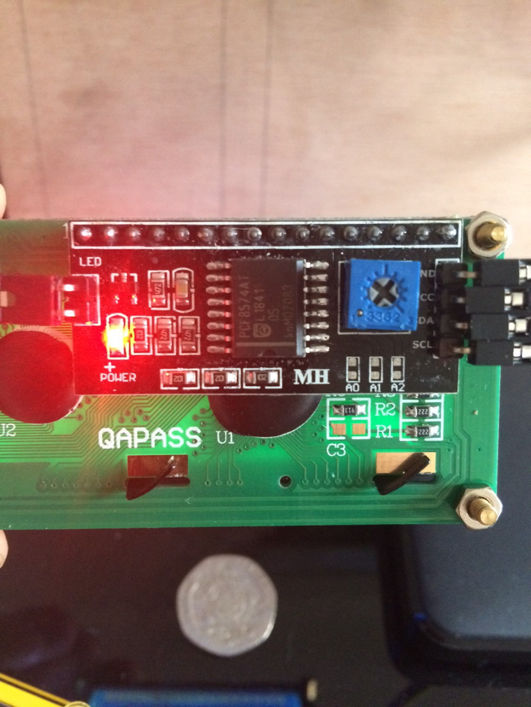
My problem is my hd44780 lcd (connected via i2c backpack) doesn't work and shows white squares (blue background). To get me on the right fault finding path does anyone know if the squares mean a hardware problem (not wired correctly/bad connection etc) or software related?
The display is supposed to show rom and emulator info.
Connecting the lcd via a breadboard isn't really an option because of lack of room in my enclosure.
According to the HiFiBerry forums I shouldn't have any GPIO conflicts.
The pins I'm using are:3-6 (hd44780)
12,35,38,40 (DAC+ Light)
24, 26 (ATXraspi)Thanks.
-
Also sudo i2cdetect -y 1 returns no address.
-
The squares mean the lcd is not initialised, this could be either hardware or software.
you could check the following:
Did you enable i2c (sudo raspi-config) ?
Is this lcd backback 3v3 compatible (or do you use a 3v3 <-> 5v level shifter) ?what software do you use to drive the lcd with ?
you could test the following:
wget https://raspberrytips.nl/files/lcdi2c.py
sudo python lcdi2c.py -
@future-child
Here the story begins...
https://retropie.org.uk/forum/topic/11485/is-sharing-i2c-pins-possible -
@cyperghost I wouldn't normally post again regarding the same topic but I feel a few things had changed.
-
@future-child Yes I have i2c enabled,
I'm not sure if the backpack is 3v compatible or not but i'll have a look.
The software I'm using is a scrolling game title script/package called RetroPie-ClcdThanks for the reply and i'll test lcdi2c.py see what happens.
-
I ran lcdi2c.py and I get: IOError: [Errno 121] Remote I/O error
I'll double check all my connections. -
@boz The lcd backpack you have would be for TTL (5V) and would require a level shifter see step 1.
Asi2cdetect -y 1returns no error it is safe to assume the /dev/i2c device exists (and therefore i2c is enabled).
Possibly you may have already damaged the i2c pins by connecting a TTL device (albeit a very small chance).to make sure all is correct on the pi side (software wise) check the following :
/etc/modulescontainsi2c-bcm2708andi2c-dev./etc/modprobe.d/raspi-blacklist.conf(if a all present) hasblacklist spi-bcm2708andblacklist i2c-bcm2708commented out with a # or not present at all./boot/config.txtcontainsdtparam=i2c1=onanddtparam=i2c_arm=on- reboot to make sure the i2c interface is enabled.
-
Ok I'm going to go through the software things you've suggested, i2cdetect -y 1 returns no error but neither does it return an address.
My i2c backpack looks the same as the one in the guide so i'll get hold of a level shifter asap.
The pins on the backpack are connected via a header on my HiFiBerry Dac+ light and not directly to the pi, so I'm thinking maybe connecting directly to the pi to rule out any soldering issues on the header (although I'm going to double check those in a minute).

-
I've just checked /etc/modules and it contains 2 instances of both i2c-bcm2708 and i2c-dev for some reason.
There are no blacklist entries in raspi-blacklist.conf.
/boot/config.txt contains the following:dtparam=i2c_arm=on
dtparam=i2c1=on
dtparam=i2s=onI think I might have added dtparam=i2s=on while trying things.
-
@Boz
No it's okay to ask for annother topic but you see I2S can sometimes be a mess. Because some devices deisgned for Arduino (5V on it's I/O Pins) will be selled for RPi also. That could work if you connect your Display to 3,3V the chance that this will work are very low. The method I introduces to you in the previous posting is, to remove I2S hat and directly connect to GPIO. Then the display runs with 5V, the GPIOs are independend and send data with 3,3V... Do not connect a output channel from LCD to GPIO 3,3V vs 5V isn't the best method.@future-child seems to have much more experience than me in wiring.
-
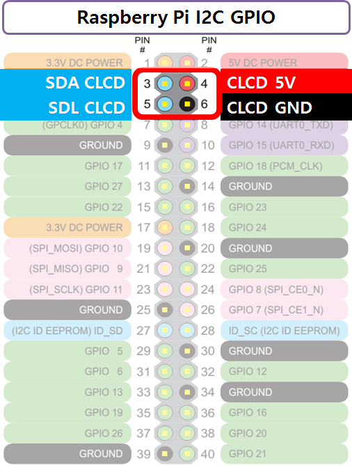
i2c does indeed seem to be a bit of a mess, just so I understand this correctly I currently have the lcd connected like this:
GND - pin 6
VCC - pin 4
SDA - pin 3
SCL - pin 5I followed this diagram:

Pin 4 shows 5v so if my backpack is TTL (5v) how does this pose a problem?
PS: Thanks for both of your help btw it's much appreciated.
-
@cyperghost I have a spare hd44780 with no backpack to wire up directly if need be, but I'm concerned I won't have room for a breadboard so I was trying to stay away from that if possible.
-
@boz The pi can output 5V as well as 3v3 but the gpio ports are only 3v3 tolerant, therefore you need a level shifter. The 5V produced by the backpack is simply to high and possibly could damage the ports.
-
Ok i'll disconnect the lcd for now until I get the level shifter (will be next week now).
Is this one ok?
https://shop.pimoroni.com/products/sparkfun-logic-level-converter-bi-directional?utm_medium=cpc&utm_source=googlepla&variant=7493045377&gclid=CjwKCAjwzMbLBRBzEiwAfFz4gQd35zRrMF0RFk7mjybTQZZHGF0hfcEVPTglsuBgr-SAGlMsuHTdDBoCKX0QAvD_BwE -
@boz Yes that one would do fine.
-
@Boz
No No! Please don't directly wire 5V to SDA/SCL! This will damage the Input GPIO! You rather should use Pin 1 for power... with much much luck it works!If you prefer easy wiring then use a I2S designed for RPi with 3,3V TTL but most LCDs need at least 5V.
Annother method could this one
You power it up with 5V to ground and the PIC "could" interpret 3,3V signals from UART of Pi.... I said "could". Usually the signal of high is 2,5-2,7V to 3,3V could work!What the difference between the UART and the I2C? The UART is a one way communication so no signal reaches the Pi and so overvoltage is no risk!
The cleanest way imho is the direct wiring! The Breadboard is just for testing. If it works you can solder it directly
-
@future-child said in What am i doing wrong with my hd44780 16x2 lcd?:
@boz The pi can output 5V as well as 3v3 but the gpio ports are only 3v3 tolerant, therefore you need a level shifter. The 5V produced by the backpack is simply to high and possibly could damage the ports.
right!
-
@cyperghost So there is already a chance that the SDA/SCL pin is damaged? If so would it have damaged the Dac+light or the pi itself?
I'm grateful that people write tutorials such as the one I followed for the display but there seems to be a lot of conflicting information out there.
So i can either go with the level shifter or the direct wiring without the backpack, I'm gonna read back through your posts and see what pins need to be connected to directly wire this.
Hopefully there has been no damage and i can carry on with my troubleshooting or better still the damn thing just works lol! -
Well I have an I2S backpack here, without LCD and I can detect it with
i2cdetect -y 1on 27h.
Try to wire the whole thing on 3,3V and take a look to the red LED. Then check withi2cdetect -y 1There are tons of "how to" connect a HD44780 on google, the poti isn't needed - it's for contrast setting
EDIT: Easier setup without resistors! This one is for Pi B, but the GPIOs are backwards compatible. This graphic is only for example! How a wiring should work! I've tested it for several years and it worked so far!

Contributions to the project are always appreciated, so if you would like to support us with a donation you can do so here.
Hosting provided by Mythic-Beasts. See the Hosting Information page for more information.