Retroflag NESPi Case - Soft Power & Reset Hack
-
@foldedpencil You are quite welcome. I am glad you got it going! As far as helping hands, I have a set but seldom use them. For me personally, it's usually easier to hold parts in place by hand although I will admit, I have calloused fingers and don't tend to get burnt easily. If you do get a set, avoid the ones that use wires as the 'arms'. They tend to have a memory to the wire and will spring out of shape easily. Look for the ones with solid metal arms and wing nuts at the joints for more precision when positioning.
-
@yahmez Thanks again! I don't mind the heat, I just don't seem to have enough hands to hold the components, the iron, and apply the solder. I feel bad detracting from the thread by asking for soldering advice. Maybe I just need to watch some more youtube videos.
-
@foldedpencil Nah, you're fine. One thing I do is unroll a short length of solder so it's sticking up and hold the board in one hand and the iron the other. Then I can heat the component and board and move them up to the solder when hot. Describing it makes me feel like maybe I'm a weirdo though lol.
-
@Yahmez - Thank you so much for putting together this wonderful tutorial, it was extremely helpful. I followed your instructions to the letter and was able to complete this hack successfully! There is one change that should be made to the PDF instructions. Since I followed your instructions exactly, I ordered the exact part numbers from Arrow. Please note, on the parts line item that reads "(3) 6” [150mm] long female dupont jumper wire" <~~ the quantity should be one, not three as this particular part number includes (20) jumper wires. I realized this when ordering, so I ordered quantity one and received a pack of 20 jumper wires from Arrow -- so I can confirm.
To all the soldering noobs out there thinking about doing this hack -- this was my first time soldering. After watching a few youtube videos on soldering techniques and taking my time following the directions exactly, I was able to pull this off correctly on my first boot-up. Take your time, order the right tools and you should be fine (a "helping hand" really was handy).
-
Hello everyone
Thank you Yahmez for the great guide and the effort you put into it.
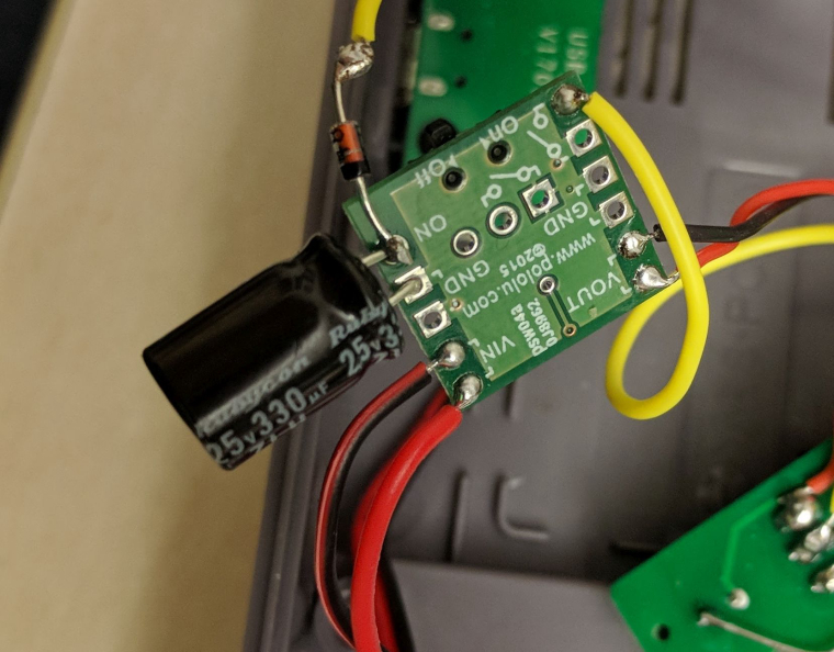
I built the thing yesterday and sadly it didn't start. The RPi didn't get any power at all.I followed your instructions exactly, apart from using another capacitor that I had lying around. I used one rated for 330uF 25V. Could this be the reason or do I have to start troubleshooting?
-
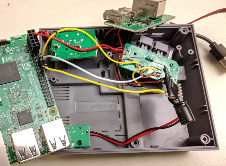
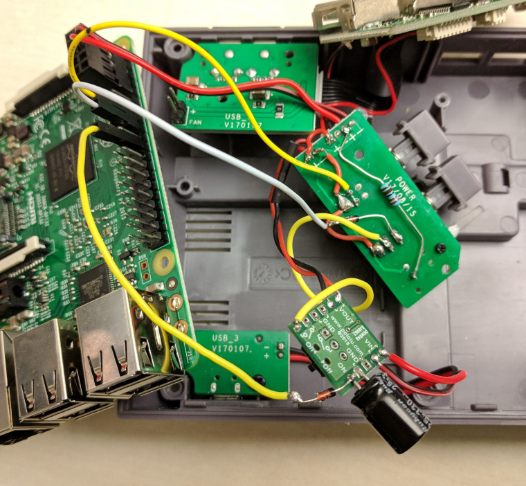
@schnautz Would you be able to take picture of all your solder connections, etc? The sizing of the cap is fine although you need to observe polarity when soldering on the mosfet board.
-
@iggy Thanks for your swift reply.
I checked the polarity of the capacitor, but thanks for the tip.
I realize my severed connections look pretty messy. But for quite some time they were still connected when I checked them for continuity.
-
@schnautz Your capacitor should be fine as long as it fits ok. Is it still not running? If not what happens exactly? Does the led on the front of the case turn on?
-
K i see whats wrong...for Vin and Vout, you neg wires need to be connected to the pad that says GND on the mosfet board.....currently, for Vin, your neg lead is connect to both pads labeled Vin. Same with Vout. Have a look at Yahmez's pics to see what Im talkin bout .
-
@iggy Ahh, i see it now. Tbh i rushed it a little bit. I guess this is what happens when you do that.
Thanks to both of you.
Edit: Workes like a charm now. Thanks again.
-
@schnautz Nice! Glad you got it sorted!
-
hi all this is my first post.
@Yahmez first of all thanks for posting your work then..I'm better at programming then electronics, so can you please explain why I need a mosfet and a diode?I cant simpli connect the power switch to GPIO? -
@Yahmez Do you happen to have a schematic of the before and after modifications? I intend to port the same type of modifications to PowerBlock unit in an NES console case Power/Reset switches.
-
@rollerace
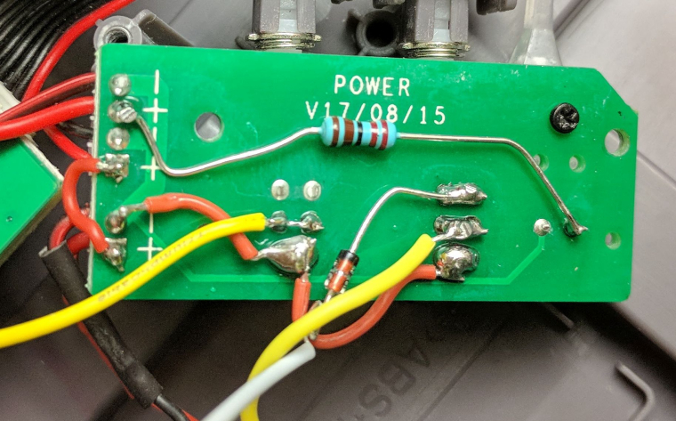
The mosfet is basically an electronic power switch, like a relay. Using it allows you to turn off the power switch and have the pi shut down and then cut the power. If you wire the power button directly to the GPIO you can still have the pi shut down but the power LED on the case will remain lit, so you would have to wire it to a gpio as well if you wanted it to turn off without unplugging the PSU. Also, even in shutdown the pi (still connected to the PSU) will continue to draw a nominal amount of current. The diodes are required to make the circuit work, blocking voltage in the required directions to allow the circuit to function the way I needed it to. -
@ortsac
I do not have a schematic drawn up, but I can tell you that the components used were chosen to work together with the Pololu mosfet board. It depends on the additional transistor switch on that board to function as I used it in the case hack. I never really drew up a schematic (although I almost always do) but I simulated the circuit instead based on the schematic provided by pololu. I might be able to draw something up for you though if I find some free time. Wondering why you are wanting to use the power brick instead of the mosfet board though... It's 5 or 6 times the price. -
I just bought this for a build for my niece's xmas gift, and when I saw how well it was made I ordered one for myself... luckily, I was about the last one before that supplier ran out. :D
Didn't know until after about the shutdown/reset issues on these. Seems a rather dumb design that could have been fixed when they came out with the new batch.
Anyways... I'm a NOOB at this stuff, so probably a stupid question I have... but... when I was looking to build an arcade cabinet, I wanted to add a power off switch and it was pretty much just a momentary switch, connected with 2 wires to the Pi and a shutdown script.
Looking at the OP, the MOD has capacitors, resistors, etc... is it more difficult than it needs to be?
Can't the buttons just be bypassed on the board, and wires going direct from the buttons to the GPIO pins? 2 wires for the power, 2 wires for the reset, and add a script?
Again, I'm a NOOB... but, without the case, adding a safe power off button was just 2 wires and a script, I don't recall seeing a tut requiring capacitors and resistors, etc...
-
@throbinson said in Retroflag NESPi Case - Soft Power & Reset Hack:
Again, I'm a NOOB... but, without the case, adding a safe power off button was just 2 wires and a script, I don't recall seeing a tut requiring capacitors and resistors, etc...
Really? It's just a question what you are want to do ;)
The solution in this video is just a "standby" shutdown. The Pi and all voltage output (means a external HDD or fan are still powered) If this is enough for you then fine :) -
@throbinson I literally just answered this question only two posts above yours. lol
-
Ah I getcha... kind of a standby or sleep mode, not a powered off mode.
Is the OP method the best one? I saw a video on that ETAPrime's YouTube chanel that looked easy enough, but also saw posts saying that it for some reason works for some people, not others.
I don't mind the extra work, and I have a big bin of caps and resistors (started to teach myself simple stuff with DIY's for guitar pedals) I just want to make sure that if there was a 'best' solution out there, that I pick the right one.
-
Contributions to the project are always appreciated, so if you would like to support us with a donation you can do so here.
Hosting provided by Mythic-Beasts. See the Hosting Information page for more information.