Wiring a joystick
-
Hi !
I'm building my first bartop using retropie, and I got a problem with the wiring of the joystick.
I am using this arcade rocker circuit board I bought from China's AliExpress.I find many documentation on how to hook up one side of the wires on the circuit board and i'm pretty sure they are correct.
The problem is I don't know how to hook those wires up to the buttons/joystick.
Each plug for each button has a blue and a white wire, and each button has only two clips to put the buttons on, wich one goes where?
Is there one contact and one ground wire?
The 4 directions of the joystick each have three clips whilst I have only 2 wires??
I read some documentation about installing a Daisy chained ground wire, but idk if this is the case cause there is nog ground GND on the circuit board.I know this is technically not a pure retropie issue, cause my retropie is working fine with any usb joystick, and the arcade rocker is also giving an error when I hook it up to the pc.
But i'm kinda clueless about what to try next to make it work.
I hope one of you guys can help, since there seem to be many people here that have built bartops/arcade machines.Thanks in advance.
-
Do you have a link to the item you bought or an Image you can post?
I can make presumptions about which pin is which but then I may lead you to the wrong conclusion, so an image will let us give you a more confident answer.
For the buttons, that is simple enough to answer;
The buttons are momentary button that complete a circuit when pressed. In this case it doesn't matter which pin goes were as one will be ground and the other POS (or NEG as some use) as you connect it to your board or encoder. It is good practice to be consistent though and if you daisy chain your ground to use the same pin on each button. This will avoid accidentally connecting the ground to a POS connection. That would result in that button being viewed as always held down.
If you had an LED button then the pins matter more, but you don't so I'm not going to go into it.
Moving on to the joystick;
Each direction is controlled by a micro switch. (Yes, there are other switch types but I am making the presumption so suck it up)
The swith has three pins for different set ups. One pin is ground or "common" one is NO "normally open" and one is NC "Normally closed". These two NO and NC pins determine what state the switch is in when "NOT" pressed. For Arcade "NO" is used most often.
You will want to determine which pin is NO and connect one wire to that and the other to COMM with the NC pin being un-used.
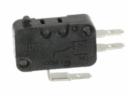
In this image it is the pin on the bottom and the lower pin on the right side.
-
Thanks for the info
Here are some pictures, the arcade stick has the same switches as the switch you posted, so the com one and the NO switch should be connected then. The No is the top one when holding the switch with the COM side up.I'll try re wiring it, even tho it is kinda hard to get those switches loose again. They fit so damn tight and i'm scared of breaking it.
Thanks for the help
-
My pictures won't show so here's the urls
https://1drv.ms/u/s!Avpe-NxF0f3Lxilkeu2tgduV01Dk
-
@mc78 said in Wiring a joystick:
Thanks for the info
Here are some pictures, the arcade stick has the same switches as the switch you posted, so the com one and the NO switch should be connected then. The No is the top one when holding the switch with the COM side up.I'll try re wiring it, even tho it is kinda hard to get those switches loose again. They fit so damn tight and i'm scared of breaking it.
Thanks for the help
Try to use some needle nose pliers or something similar to just edge them off, and don't pull them by the wire itself as these tend to break. It looks like you've got them wired up correctly, but if it's not working I'd hazard a guess that even though you've put them on the right pins, they could be the wrong way round.
-
I had all the blue wires on top on the COM side, and just with one I had the blue wire below on the ON side, I'll try switching this one to make it the same on all switches, don't know if that matters, but might as well try that, and switching them around afterwards
-
With the images I can confidently add a few more details to my advice.
Before I said the wires on the button don't matter. This is still true BUT the usb encoder you have will have one pin on those two pin connectors assigned to ground and it is shared. So Like I have said before it will be important that the button are consistently wired the same. In your case the buttons are using micro switches like the joystick but with the NC pin removed.
The same logic applies to the joystick. So with the exception of the stray button wired backward from the rest it looks consistent.
If it doesn't work it is worth reversing the wiring in the event these are diode switches and current is only able to flow one way.
Worst case, you post your failures for all to see. and then we will try somethings else.
-
Ok thanks again for being such a great help
I'll try this weekend and let you know if it's a failure or succes :)
-
I got it working and can continue my build project !!
It worked when I put all the white wires on top on the COM side, and the blue ones on the NO side of the switch.
When I my project is finished I'll show ya'll what i've made on the project builds pages of this forum
Thanks again for being such a great help!
Contributions to the project are always appreciated, so if you would like to support us with a donation you can do so here.
Hosting provided by Mythic-Beasts. See the Hosting Information page for more information.