PSPi Version 2.0 - Raspberry Pi Zero in a PSP - Project is Now Complete!
-
@johnweland
Yea it's just got the one on each side, not the dual setup like the XboxI'm starting a discussion in the forum.
-
@adamspc just for the record, I am totally interested in the pcb route if you are seriously considering designing one.
-
@markyh444
It's official, I'm doing it. Too many people have asked so I can't say no. I hope to make it a group activity, so anyone with PCB design experience or anything helpful to add please visit the this forum to participate. -
i would definitely buy a couple boards. i have 2 old dead psps that would make good donors :D
-
@84TAVeRT Sounds good. All my focus is on designing the board right now.
-
@adamspc
Hi I've started the build, but haven't got to connecting the fpc cables to the pi yet.Is it worth waiting for this pcb you're designing? Do you know timescales yet.
Thanks
-
@adcraggles
It's hard to give a good estimate. I can say that once the design is finished it'll take a couple weeks to get it made and then it needs to be tested. I'm still at least a couple weeks from finishing the design, and some of the circuits are still being designed. I'll post an update when I have a better estimate. -
Thanks mate,
I think I'll wait as I'm making 3, 2 for Xmas presents and 2 for myself.Goodluck
-
@adcraggles 1 for myself I meant
-
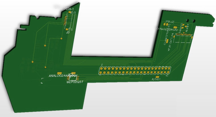
Hey guys, just updating to say I'm considering PSPi Version 2 to be complete. The custom PCB is being designed, and I'm planning to use it for Version 3. Follow along and get involved at my site.
-
I made a Youtube video showing Version 2 in action.
-
Wow, now I'm thinking that I may go this route for my portable instead of a Gameboy Advance. That's really slick.
-
Yeah its pretty Slick!! Have you got the analogue sticks working?
-
@moosepr I'm working on it, but I probably won't add it to this one. I'm wiring up an analog/digital converter that converts the stick position (Ohm value) to a series of button presses. There is a little bit of hardware and a lot of software work left before I'm happy with it. I was just ready to have this finished, so I moved it to Version 3. I'll post a guide on my site once I have it working the way I want.
-
@adamspc not sure on your plans for the analog to digital conversion, but can highly recommend these
it is essentially an arduino leonardo, so you would be able to program it to read the analogue inputs, and convert them to keyboard commands to be sent to the pi via usb. The only problem with that, it would mess up your usb socket on the top.
-
@moosepr Very cool. That would definitely simplify everything. I'm trying to avoid using a USB hub in this project, so yea this would probably be a no-go. I've got options though. I'm using an MCP3002, and I've already added it to my PCB.

-
@adamspc
I'm sure I used the same car monitor as you in my build. But I power this one with 12V and then convert to 5V.
I als use the same PAM audio module as you in your build but I'm running in audio troubles. There is some noise during startup and loading games (always if the Pi acts) - the in game sound itself is quite fine, but it's annoying in idle.Can you please take a look to my build: Popeye Pi and help me out? Maybe I setted something wrong in the command.txt? I just use mono audio and used GPIO18.
What GPIOs are you using? -
@cyperghost
I'm troubleshooting the same idle noise you are. I've resolved it temporarily by setting the OS volume at 100% and adding a resistor(150-250ohm) in series with each audio channel between the amplifier and speaker. This makes the noise far less audible, but makes your max volume lower. This is only a temporary solution, and I'm working on a permanent one.Things I've tried:
- Different high/low-pass filters on the PWM
- Different high/low-pass filters on the PAM8403 output
- Ferrites on PWM and PAM8403 output
Things I'm going to try:
- Small capacitor and ferrite together on the amp output (waiting on parts)
- Capacitor on 3v3 line. The noise seems to be coming from the CPU and SD card activity, and I'm wondering whether leveling the voltage out will remedy the noise somewhat.
- Larger inductors on the PWM and PAM8403 output
- Band stop filter at the specific frequency that is giving the noise
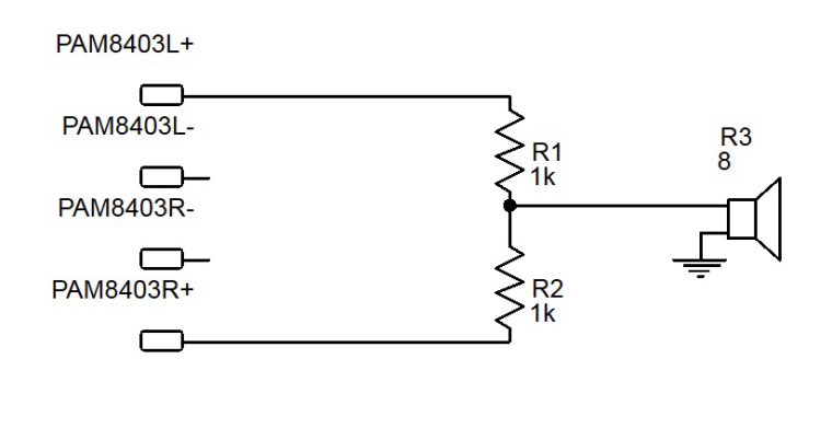
I'm using GPIO 13 and 18. I also see that you're trying to bridge the audio channels instead of using two speakers. I read somewhere that you can take both positive outputs from the amplifier and connect them to two resistors in series, and then the connection point between the two resistors goes to the speaker. Something like this. I cannot remember where I saw it. This would also double as the resistor needed to lower the idle noise. Maybe try 150-250ohm. Worse case scenario you damage the $1 amp.

-
I also see that you're trying to bridge the audio channels instead of using two speakers
No, not now. I don't want to solder a second audio channel.
Maybe it's possible to downmix by software :)A solution (I also wrote in my guide) is to use annother audio module
https://www.adafruit.com/products/3006
What do you think?I tried
- annother PAM module (red board)
- Bridged ground and PWM together with 47k resistor to resolve currents with the RC-filter
- shielding with metal mesh stripes (used for shield wires)...
Maybe the Adafruit is going better?
Thanks for the quick respone :)
Congrats for your nice build, it is a pleasure to visit your homepage -
@cyperghost
Not sure about the software downmixing. Sounds doable. I saw that Adafruit module a while back and I've wanted to try it. A pure digital solution sounds like a good one. Only reason I haven't done it yet is because I would need two of them and I've already spent way, way, way too much money building this project.
Contributions to the project are always appreciated, so if you would like to support us with a donation you can do so here.
Hosting provided by Mythic-Beasts. See the Hosting Information page for more information.