Pi in a Gameboy Advance Build - WIP
-
If I can fit it in an Altoids tin you can make it work in a GBA. I can't wait to see what you come up with. Good luck dude I believe in you =]
-
@obsidianspider yeah that was where I got stuck! I did some digging and it looked to me that the PCB did very little other than making the ribbon cable more breadboard friendly, and adding the SD card. I did make a custom PCB that the screen could be transplanted on to, but life has gotten in the way and it's sat in a box untested
want to get a tft into your project, look no further than here https://retropie.org.uk/forum/topic/7464/ili9341-tft-screen-guide
-
@moosepr I think I'm going to try the 3.2" Sainsmart display that Tekkaman_Slade used on their NeoPiGamer. The 3.2" will just fit if I trim off the extra buttons, and I don't see any way a 3.5" backup camera screen will fit. The 2.8" screens are slightly smaller than the opening in the GBA screen cover, and I think that might look a little janky.
Now I need to find a small USB hub…
-
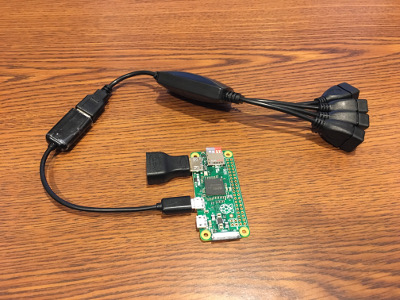
I ordered the Sainsmart 3.2" screen as well as a 4-port "octopus" (quadropus?) hub that I saw on the sudomod wiki
Assuming the hub works like I want it to (keyboard, wifi, controller, usb drive), I'll take it apart and just keep the board and then wire it up to whatever ports or boards I need.
-
Since I don't have a USB hub, and I only just ordered the one for this project this morning, today I decided use my Pi 2 as a test platform to see if the old USB sound card that I had sitting in a drawer from a long discarded headset would work for this project.
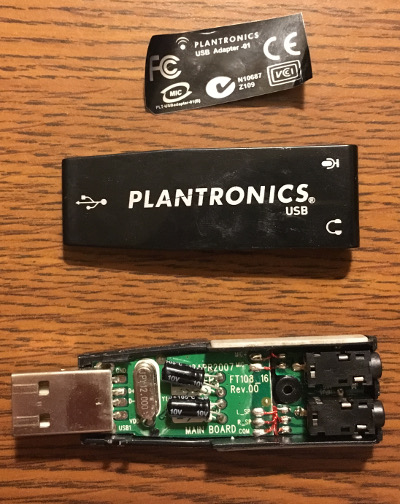
The overall adapter was a bit long for the project, but I can desolder the USB connector and the 3.5mm jacks and it'll be plenty small.
Using the instructions I found over at sudomod I was able to get the sound card working in minutes. With headphones plugged in it was LOUD (I'm not sure how to set a hotkey to do the
Select+ UpSelect+Downto adjust volume like I've heard some people refer to so I went though the RetroPie menu and adjusted it there for now) so hopefully it'll do well to power the GBA speaker. -
@obsidianspider
This is what I did with my Xbox 360 controller which will adjust the volume with RetroArch emulators:
sudo nano /opt/retropie/configs/all/retroarch.cfg# Volume controls: mute, volume up and down input_audio_mute_axis = +1 #Down on D pad/Left Stick input_volume_up_axis = -3 #Up on Right Stick input_volume_down_axis = +3 #Down on Right Stick -
@backstander said in Pi in a Gameboy Advance Build:
Thanks! Do you have to hitSelectto activate that, or is it just any time you hit up on the analog stick it adjusts the audio? -
@obsidianspider oh yeah I forgot to put the hotkey button. Yes you would need to hold the
Selectbutton to activate it.Config it like this:
# Hotkey button input_enable_hotkey_btn = 8 #Select -
@backstander That makes sense.
Now I need to get back to Strato Fighter!
-
I never realized how often I try to use a network connection to do things with my Pi until I had a Pi with no network connection. That's it, the handheld is getting Wifi.
Hackaday has a really good writeup of adding an Edimax wifi adapter to a Zero. This will be done once I have my hub and am sure that it works before cutting it apart.
-
After getting frustrated with my multimeter trying to figure out the wiring for the potentiometer (volume knob) I found a diagram over at Assembler Games and it looks like the pot is controlling the "volume" pin of the amp chip. I'm not sure I want to go through the trouble of trying to keep the GBA amp functional, especially when a stereo potentiometer is around $1. If someone figured that out, I'm all ears, but I think it may be more trouble than it's worth.
-
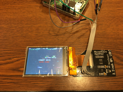
My SainSmart 3.2" TFT showed up today and getting it to work wasn't as straightforward as I initially read, but it was totally doable and the speed seems very good when connected to my test mule Raspberry Pi 2 with a fresh image of RetroPie updated to 4.0.6.
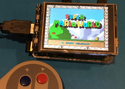
(I still have the protective film in place)OK, so here's how I got the screen working on a freshly installed image of RetroPie 4.0.6 on a Raspberry Pi 2. Steps are a combination of a few posts here and on GitHub
First I added the following to the bottom of the
/boot/config.txt#Waveshare 3.2 TFT Screen #same resolution for hdmi and tft hdmi_force_hotplug=1 hdmi_cvt=320 240 60 1 0 0 0 hdmi_group=2 hdmi_mode=1 hdmi_mode=87 dtparam=spi=on dtoverlay=waveshare32b:rotate=270,speed=82000000,fps=60Then I rebooted and wondered why nothing had happened. It turned out I needed to install the device tree overlay (that's what
dtoverlaymeans, you learn something every day). Since RetroPie isgit clone https://github.com/swkim01/waveshare-dtoverlays.git sudo cp waveshare-dtoverlays/waveshare32b-overlay.dtb /boot/overlays/waveshare32b.dtboI rebooted and my screen was still black. What the heck? It turns out that by default Linux is blanking the second screen when displaying on the primary framebuffer (the HDMI port). To confirm that your screen is being recognized as
fb1you can run the following commandls /dev/fb*and you should see
/dev/fb0 /dev/fb1fb0is the HDMI display andfb1is the TFTTo get the data from fb0 to display on fb1 there's a framebuffer copy utility that you can install
sudo apt-get install cmake
git clone https://github.com/tasanakorn/rpi-fbcp
cd rpi-fbcp/
mkdir build
cd build/
cmake ..
make
sudo install fbcp /usr/local/bin/fbcp
You don't want to run that manually every time you boot, so we can do that by adding a line to
/etc/rc.localsudo nano /etc/rc.localBefore, the final “exit 0” line, add the following:
/usr/local/bin/fbcp &Ctrl+XthenythenEnterI also think I blacklisted the touchscreen driver to prevent possible goofiness and also to potentially reduce CPU load.
sudo nano /etc/modprobe.d/raspi-blacklist.conf(Mine was blank)
Add
# 3.2" LCD Touchscreen driver blacklist ads7846Ctrl+XthenythenEnterThen reboot to implement everything
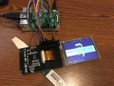
sudo rebootIf all is well you should see your screen displaying EmulationStation!
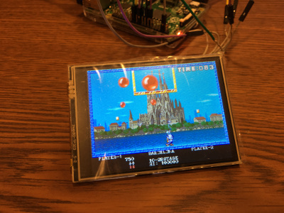
I don't know how to detect FPS, but it is very playable. Definitely preferable to the fuzziness I've seen in photographs of using a backup camera monitor.
Next I need to try to get it working on the Pi Zero before I attempt to chop it down to fit the Gameboy Advance case.
-
@obsidianspider do you notice any shearing or tearing on the screen when it's doing fast and full screen updates? I get it on the ili9341 tft but it's not too bad
want to get a tft into your project, look no further than here https://retropie.org.uk/forum/topic/7464/ili9341-tft-screen-guide
-
A little bit of tearing in EmulationStation, but in games it's super smooth. Even with some Sonic the Hedgehog it's great. Granted, this is on a Pi 2. We'll see what happens when I connect it to a Zero.
The only annoying thing is the 320x240 compression of some fonts and such, but that's because it's low resolution, not because it's broken. I get that same effect on a "real" tv.
-
@obsidianspider yeah the older games didnt have massive resolution anyway, so they look fine. I found the handheld games look better, because they were designed to be viwed on the smaller screens, but playing a game designed to be viewed on a tv can be a bit fuzzy
Used to own a game gear back in the day (its still in the loft) and that had an adaptor to let you play master system games. I remember having the same issue when playing master system sonic, on a game gear. lots of squinty text
-
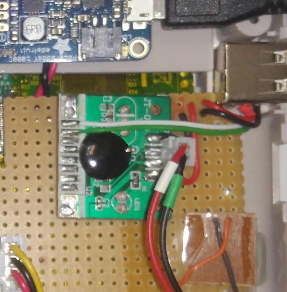
http://www.stuffaboutcode.com/2016/01/pocket-pigrrl-battery-monitor.html
Found this while hunting for some Low Power LED wiring diagrams. Thought this might help!
If you can make heads or tails of this little strip he wired up please let me know hah
Not all those who wander are lost
-
I don't want the big plastic GPIO connector on the back of the screen when it's in the Gameboy, so I decided to try to figure out what pins were necessary to make it work as opposed to the ones that were "just there" because it's mean to just plug right in. The SainSmart web page for the screen had some pinout information, but didn't list what the pins were actually numbered, so it wasn't really helpful. Since the SainSmart screen is a clone of the Waveshare I went looking for pinout information for that and I was in luck. The Waveshare page has pinout information with pin numbers. I put a screen shot below just in case that web page goes away in the future.
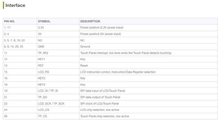
I don't want to use the buttons or the touch screen, so pins associated with those were easy to dismiss, as well as the "NC" pins. It also looks like there is a lot of power and ground redundancy going on. I wasn't sure if the screen ran off 3.3V or 5V so I connected up one 3.3V, one 5V and one ground pin, leaving the redundant power pins disconnected. The screen worked the same as it had when directly plugged in, so that was a good sign. I tried removing the 5V power and booted the Pi and the screen didn't come on at all. I connected the 5V and then disconnected the 3.3V pin and the screen works correctly. It looks like it runs on 5V. What I don't love is that the 5V pins on the Pi are "hot" all the time, so the backlight is on whenever there is power to the Pi. Just for the heck of it I tried connecting the 5V pin from the screen to the 3.3V pin on the Pi and it didn't work. But it was worth a try.
This is how I have the screen wired and working properly on my Pi 2 test system.
Pin No    Symbol           Description
4         5V               Power Positive (5V Power Input)
13        RST              Reset
15        LCD_RS           LCD Instruction Control, Instruction/Data Register Selection
19        LCD_SI/TP_SI     SPI Data Input of LCD/Touch Panel
20        GND              Ground
23        LCD_SCK/TP_SCK   SPI Clock of LCD/Touch Panel
24        LCD_CS           LCD Chip Selection, Low Active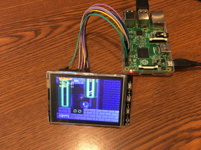
-
@monstermadeofman Ooh I like it. Definitely a good way to show that information, but I was thinking maybe a multicolor LED status would be "better" like adamspc used in their PSPi, though I haven't gotten to power stuff yet. Though I do want a "soft shutdown." adamspc has a simple and advanced version explained on their website. I also saw two versions in the forums over at sudomod that are worth investigating.
I did see that Arrow is giving away a Pi 3 with any orders over $3.14 for the next few days (It seems like a limit of 1000 free Pis per day, so I'll try again tomorrow) so it has me thinking about trying to cram a 3 in this thing if I can get one cheap. If I desolder the high stuff and cut the board down to where the test pads are for the USB ports it'll just fit if I rotate it… But my bigger concern than space would be power usage. As we all know a Pi 3 uses a lot of juice and I don't know of a power booster that can supply that much oomph or a battery that would last more than a few minutes. But it's fun to think about, especially since this Wii U controller with a Pi 3 is doing it.
Edit: I see they're using a PowerBoost 1000 Basic which can output 4A but doesn't have a charging circuit. To get around it a separate charging circuit was used. The PowerBoost 1000C can only output 2A (1 A to the battery, the other 1A to the connected device)
-
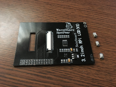
With the TFT working, now it was time to trim the PCB so it wouldn't stick out past the screen edge.
First I carefully pried the screen away from the board with a plastic spudger.
I then used Goof Off to remove the residue from the double-stick foam that was used to adhere the screen to the board.
With the board and screen clean I desoldered the switches (who knows, I may use them at some time in the future) and the GPIO connector.
Then it was time for some weight reduction. With a pair of tin snips I trimmed the board down and dressed the edges with my Dremel. I then took some ribbon cable and soldered only the contacts that I knew I would be using.
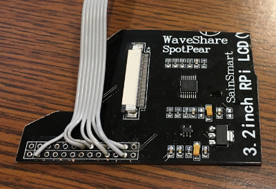
With the wires soldered to the board I plugged in the screen and hooked the wires up to my Pi 2 and…
…it didn't turn on.
At first I thought I cut something I shouldn't have in the board, or that I damaged the ribbon cable. After way too long with my multimeter testing voltages it turned out that I just had the wires connected to the Pi backwards. Luckily I didn't fry anything. Oops
With the screen and the trimmed board now working I put a piece of electrical tape over the back of the GPIO holes (the back of the screen is metal) and then attached the screen to the board with a piece of double-sided packing tape.

The USB hub I ordered came today and I tried connecting it to my Zero and sure enough, it didn't work. Things were initially looking promising with the Wifi dongle blinking during boot, then the wifi dongle went dark and EmulationStation didn't see my controller. I connected the hub to a "real computer" and plugged in four USB sticks at the same time and all were detected, so I am convinced the hub works. I'm thinking that the Pi is just not feeding the USB port enough voltage. I am going to connect a full-size USB port to the zero with power being tapped from GPIO to see if that makes the hub work before I try taking it apart, but that won't be tonight.
-
@obsidianspider there is lots of sockets to fit in the case there!!! Your screen is not using many GPIO, there will be plenty left for buttons O:-) im sure i say that to everyone!! although i think you are using the usb for sound too so that may kill my plans.
You can get OTG hubs that will negate some of the connections you have there (http://www.ebay.co.uk/itm/331758527958 first on i found on da'bay) that does have a power input, which may solve the issues you are having? i do have one somewhere, i will see if i can dig it out and have a play
want to get a tft into your project, look no further than here https://retropie.org.uk/forum/topic/7464/ili9341-tft-screen-guide
Contributions to the project are always appreciated, so if you would like to support us with a donation you can do so here.
Hosting provided by Mythic-Beasts. See the Hosting Information page for more information.