Pi in a Gameboy Advance Build - WIP
-
@diegzumillo
Sorry, I didn't get you :D -
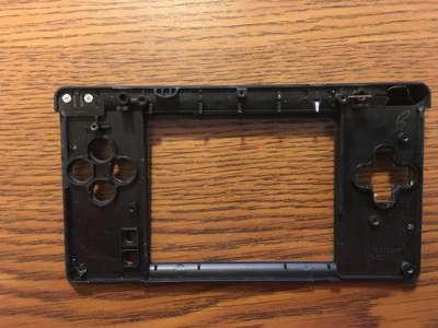
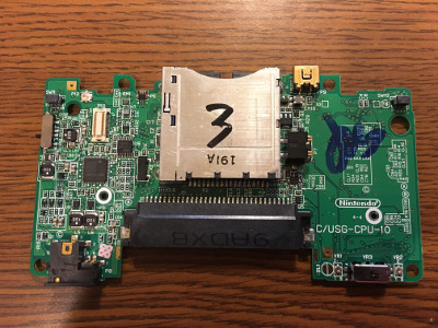
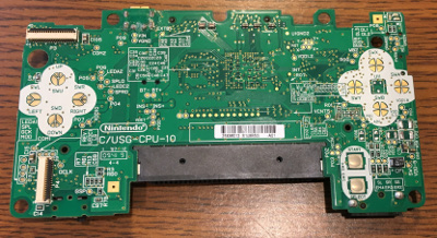
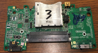
The broken DS Lite I bought on eBay showed up today.
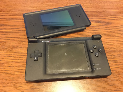
Using two guides over at iFixit I had the DS Lite apart in minutes. If I was actually trying to put it back together again I could see it taking much longer.
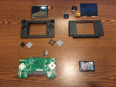
I'm mainly concerned with the ABXY button area and that part of the circuit board, but I've read that the DS Lite speakers sound pretty good, so hopefully these aren't blown. It also had the 1000mAh 3.7V battery inside, so I may mess around with that a bit during my initial testing of going on battery power.
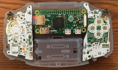
It looks like I'll be able to section out the ABXY area of the case and frankencase it into the GBA case
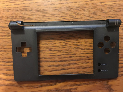
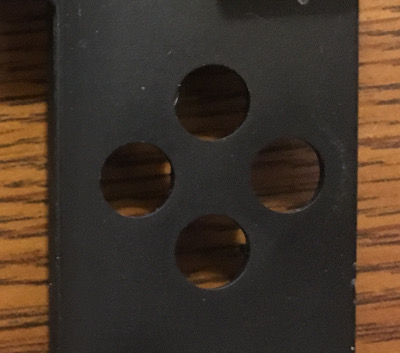
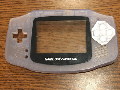
I took a piece of scrap paper and did a rubbing of the button holes from the DS Lite and placed it on the GBA case and it is like it was made for it.
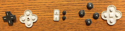
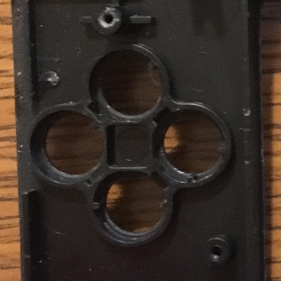
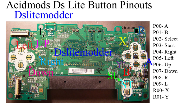
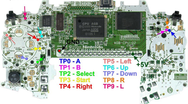
Next I'm going to see if I can wire up the
ABXYbuttons from the DS Lite and the directional,L,R,Start, andSelectbuttons from the GBA. I found some pinouts on a few different websites.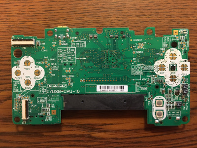
With how thin the DS casing is I'm thinking I will be able to put the DS Lite PCB on top of the GBA PCB and that extra depth should make up the difference in case thickness. At least that's the theory.
Onward.
-
@obsidianspider looking good dude! I did think those nds buttons would be a good fit for the GBA
want to get a tft into your project, look no further than here https://retropie.org.uk/forum/topic/7464/ili9341-tft-screen-guide
-
@moosepr The trick now will be to modify the case and not have it come out looking horrible. First though, I'll tackle the buttons. There are a ton of resistors, capacitors and ICs on the back and I want to cut the button pad area down pretty hard, but I also don't want to wreck a trace.
-
@obsidianspider yeah that was always my worry. the texture on the GBA is a nice and smooth, but with an obvious texture. there are some online that have the whole 'sucked toffee' look to them, and loose the whole 'factory finish' there are of course ways to get texture. There are even the totally random stone effect paints that could actually be that weird kind of cool
-
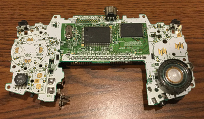
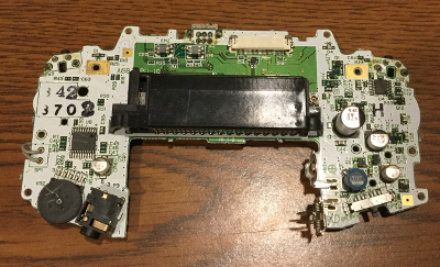
Today I decided to start working on getting the boards trimmed down. First I desoldered all of the "stuff" that I wouldn't be using (capacitors, resistors, ICs) from the PCBs. Some didn't go very well, but I really only care about the button pads for the most part.
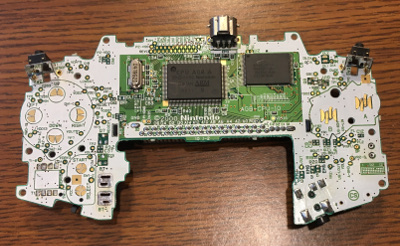
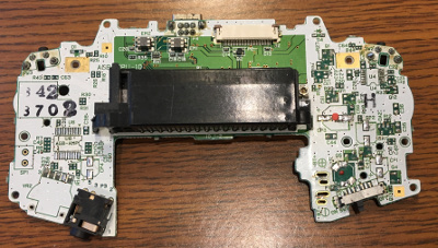
Then I cut things down with my Dremel.
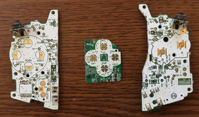
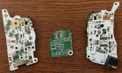
A test fit shows that things look pretty good.
I was hoping to reuse the red, green, and orange LEDs from the DS Lite for power, low battery, and charging, but it looks like the green LED is burned out. Oh well, I'm definitely already getting my $7 worth out of the unit.
-
To anyone who thinks this stuff is easy, it's not. I've been frustrated with this project the past few days. The whole "fit ten pounds of stuff in a five pound bag" is becoming very real. I ordered a volume potentiometer, but just discovered the factory headphone jack isn't going to work how I need it to, so I'm back to figuring that out. The fun is in figuring it out, but sometimes it's not as easy as others.
-
@obsidianspider I was actually thinking the same on my handheld build. Even though I wasn't squeezing stuff into a case, I still had problems to solve. I might even go as far as to say that I enjoyed making it, more than I enjoy playing the games on it!
want to get a tft into your project, look no further than here https://retropie.org.uk/forum/topic/7464/ili9341-tft-screen-guide
-
@moosepr The volume wheel showed up today, but I'm still kind of burnt out. That said, I also ordered a USB hub with a built-in ethernet switch and I put a Pi Zero in there today to act as a Pi-Hole server. It was a good learning experience of fitting small things in a case together.
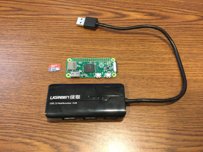
It went OK. Not as perfectly as I would have liked (I had to remove a USB port to get it to close), but it worked. It's powered by the USB plug via a USB port on my router and the ethernet plugs back into the router. No external power supply. :)
-
@obsidianspider thanks for the extensive guide. I have two of these screens i bought quite a while ago. I was able to get them to run raspbian on them but not retropie. At the time everything i read said they wouldnt work on retropie. So ive just held onto them and am planning on doing a handheld sometime soon.
-
@obsidianspider on my pi zeros i use a rockband usb hub that has 4 ports in a row but does not use a power brick. Dont buy the one with three hubs in the front and one in the back. There is a powered 4 in a row rockband hub that you dont want. The one you want says 4 port hub.... all on one line on the top of it.
-
@edmaul69 One reason I went with the 3.2 over the 2.8 (which would probably fit better) is because of the support for it. The 2.8 can work, but the 3.2 has a higher refresh rate.
-
@obsidianspider how's the case chopping going dude?
want to get a tft into your project, look no further than here https://retropie.org.uk/forum/topic/7464/ili9341-tft-screen-guide
-
@moosepr I've had a lot going on the past week or so, and I wasn't able to give the project any attention.
This weekend I'm going to work on the audio circuitry so I can see how that's going to fit. I am probably going to need a different headphone jack along with the new volume wheel I got, and I need to determine where everything is going to go inside the case before i start cutting away at the outside.
-
It's been a pretty productive morning. I won't be able to use the stock Gameboy Advance headphone jack because of how it's set up (it doesn't have an output, just a trigger for the GBA amp to switch to the speaker) so I ordered some headphone jacks from China that will be here in a few weeks. I also ordered a power strip PCB and it was incredibly cheap. Now I see why people start messing with custom PCBs…
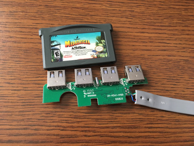
I also ordered a micro USB breakout, a PowerBoost 1000c, and a 2500mAh battery to see about cramming that stuff in. I think this is going to work. The plan right now is to put the audio circuitry on one side and all of the power "stuff" on the other, with the Zero and battery behind the screen, and micro USB charging in the place where the stock GBA communication port is and a USB A connector (or two? maybe put the USB hub at the top?) in the GBA game that I bought so I can plug in a keyboard or whatever. I still have to see about the best placement for the USB hub, but I'll have a better idea on that once the battery and PowerBoost arrive.
-
@diegzumillo That's interesting, I saw someone make a Pi3 handheld, and according to his parts list, he used a powerboost 1000c. On the video it seemed to work fine so maybe it's a bit hit and miss.
-
@jb32647
I might have seen that same video. I even asked him about it and he confirmed it was a pi 3 with a powerboost 1000. I really don't know what to make of that either. I tested it myself and it doesn't work, the Adafruit technicians confirmed it doesn't work. Maybe he had a pi2 instead and didn't know? they look the same. -
@diegzumillo the Powerboost 1000 is different than the Powerboost 1000c. From what I understand, the Powerboost 1000 Basic can output a lot more than the Powerboost 1000c but the C can do charging.
-
@obsidianspider
Yes, but it can't charge. That's a bummer. You could have it so it switches between charging and powering with a toggle I guess. In the video I'm talking about it was definitely a chargeable powerboost as well. Even though he didn't show or gave the parts list you can zoom in and see the ports.I don't know. I also noticed with mine that a lot of power is lost on the wiring. A surprising amount of it! I used to have the rainbow square blinking occasionally, then I increased the wire just to be able to move things inside the casing a little bit, and now the rainbow square is always there. So maybe if you keep your wires as short as possible it could even work with the 1000c.
-
@diegzumillo Part of the problem with the power is the size of the wire used for power. When I would mock up a build and have everything spread out on my bench using thin jumper wire I would have the low power square all the time. But on the final build I would tighten everything up and increase the gauge on the power feed it was fine.
Contributions to the project are always appreciated, so if you would like to support us with a donation you can do so here.
Hosting provided by Mythic-Beasts. See the Hosting Information page for more information.