Pi Zero W GBA [BUILD]
-
@moosepr
Um it doesn't look right to me. I will upload my schematic to show you what mine looks like. -
@moosepr
Wow. I've been so busy. I finally have time to finish this project.
Your pinout matchs up with mine. 10-18 though, I have no idea what each is for unless they operate the touch sensor.
1-9 is what I had connected that didn't work.I've soldered the screen back to the board successfully and now all that happens is the backlight gets powered, nothing else.
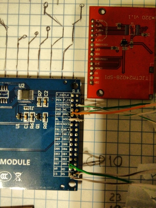
I've tried the 3.2" model too and without knowing what SCK (SCL) is and where it is I've left it not connected. Now all that happens is a powered the backlight.
I need a reference guide to what names mean the same on the pins since they are all named something else on different boards.
-
https://goo.gl/xTw5Lj Here are my pics
-
@techieandroid ok, so the last 4 pins are for touch, then all the led pins are for the backlight. Try this
Display--------Raspberry Pi
SCK------------pin 23 (GPIO 11)
SDO----------pin 21 (GPIO 9)
SDA----------pin 19 (GPIO 10)
CS--------------pin 24 (GPIO 8)
RST------------pin 22 (GPIO 25)
D/C-------------pin 18 (GPIO 24)
VIN-------------pin 17 (3.3v)
GND-----------pin 20 (GND)
LEDA----------3.3v via a resistor (10 ohm is enough)
LEDK1-4-----GND -
@moosepr
I thought you'd let me know what SCK was on my other screen (the 3.2")... Let me grab a pic so that you can see it.As far as what you have there, I already knew what GPIO pins to use, that's how it was working before I separated the 2.8" one from the board.
I don't need LEDA or LEDK1-4 because I wasn't using them in the first place.
Hope that clears things up.
-
-
I don't see SCK on this board so what is it labeled as? Or am I wrong, do I not need SCK?
-
@techieandroid i was talking about the bare ribbon on the 2.8" screen
Im not sure on the 3.2" screen, there is 'CLK' up in the top right, but that may be just for the SD card slot (along with the MOSI and MISO)
-
@moosepr
Okay, maybe I'll figure it out. I don't think CLK is it since the pins are grouped, I believe those four up there are just for the touch screen. -
Okay, so, a LOT has happened since I last commented here.
The GBA shell is almost ready to mount everything in.
I have all my components, except for the boards I'm making (explained below).
I do need some nicer wires than what I've been using, some for running + & - (I want these to be colored red and black respectively to help me distinguish my setup during the build) and some others for general connections.
I'd also like some advice on painting my GBA shell since I plan to do that as well.I've been designing my own controller boards since, the other day when I was soldering to the original GBA board (for the controller connections) the wire got moved just a hair and ripped the contact right off the board.
Now I've almost gotten to the point of having them fabricated, and I'm wondering to myself how to route the stereo audio channels from the RP0 to my TRS jack, I'm also wanting to use the volume adjustment wheel I salvaged from the GBA (since if I don't there will be a empty opening on the shell where it should've been).
My goal is to make these boards with through holes (for the connections) for easy wiring, and also to eliminate some space normally taken up by having a lot of wires every where.
And I believe that's everything. Hopefully someone can help me out on these final things.
-
Sorry to continue bothering you, I thought that you'd probably be the most knowledgeable person in this area though.
I'm thinking about going back to trying to get the 3.2" screen working, and I think either with this driver pre-installed, or with minor modifications it'll work.
I got the audio dilemma solved I think. Here's what I plan on doing:
https://learn.adafruit.com/adding-basic-audio-ouput-to-raspberry-pi-zero/pi-zero-pwm-audio
Then route the channels from those GPIO pins to the analog TR on the jack on my board.
Here's my schematic. Do note that I still need to adjust it to fit the shell just right.
I'm open to advice.
-
@techieandroid your best bet with the 3.2" screen, is to find a datasheet for it. There are normally some pins on the screen that allow you alter the configuration. Sometimes its just a case of connecting a pin to gnd or vcc to put it in spi mode
-
-
@techieandroid the listing says that screen is ILI9341 so it should just be a quick swap with the one you already have :)
-
Okay I've almost finished my long dead project but I'm having trouble wiring in the GBA's controller board into the Pi in a way that it recognizes it as a configurable controller. Can I do this or am I trying to do something that's simply not possible?
Contributions to the project are always appreciated, so if you would like to support us with a donation you can do so here.
Hosting provided by Mythic-Beasts. See the Hosting Information page for more information.