Roadcase (somewhat) Portable Arcade
-
Box built, power panel installed. The Display is now resting in place and the Raspberry Pi is mounted.
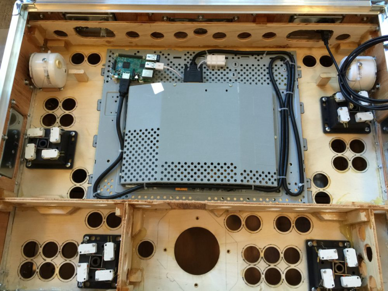
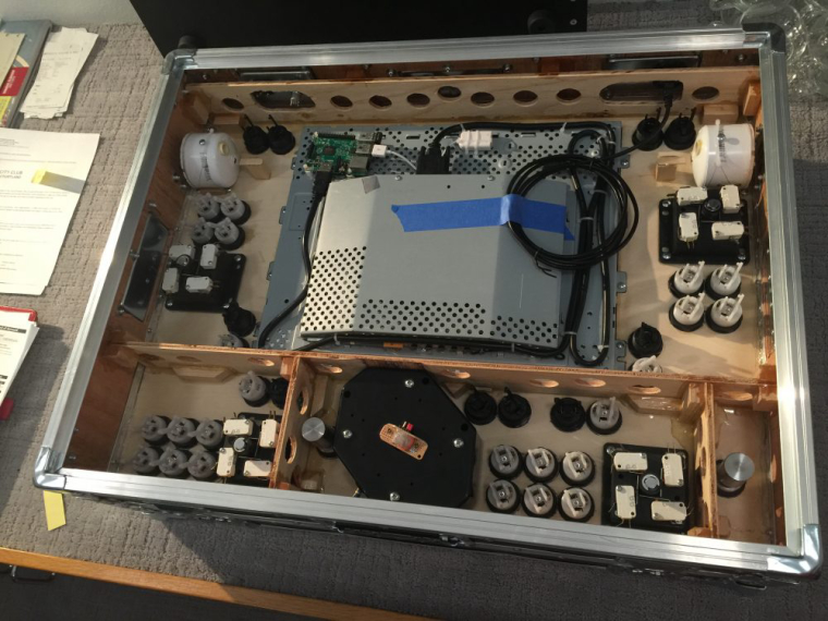
The buttons are now installed. Soon, IPAC 4, power strip, USB Hub, U-Trak and spinners interfaces. . .then the long process of wiring.
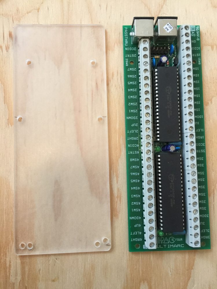
I made a mounting bracket for the IPAC to keep it from shorting against the display:
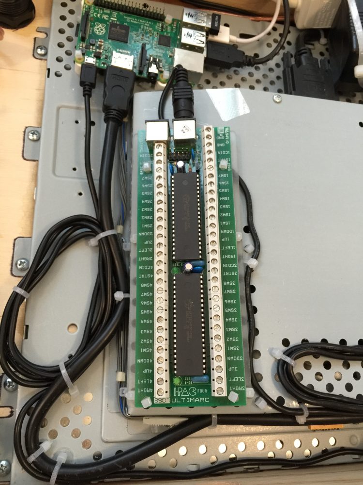
Mounting the IPAC4:
-
Wiring the pushbuttons and joysticks:
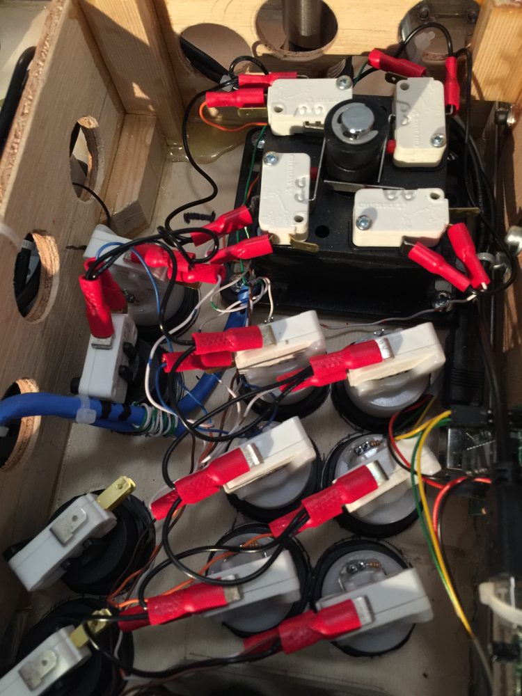
Wiring complete. This is the inside with everything done, including the power for the LED lighting.
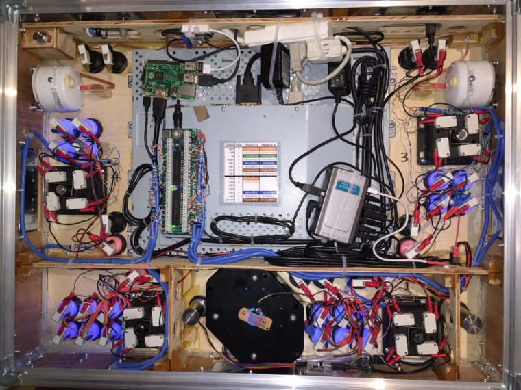
-
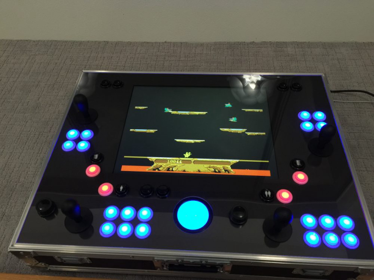
The build is finished! This image shows early gameplay tests using AdvanceMAME:
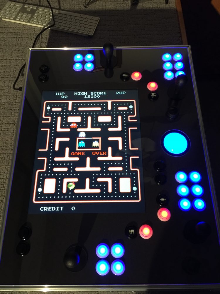
Vertical games play in cocktail mode from the player 3 and 4 positions on the sides:
-
@caver01 Awesome! Great idea implemented excellently and explained wonderfully. Thank you! I'm looking to upgrade a cabinet I built about 6 or 7 years ago.
-
really really nice!
-
@dankcushions @93sugar Thanks!
-
Absolutely AMAZING project build!!!
Props man, I am seriously impressed and ever so slightly jealous lol :))
-
@PingSpike Thanks! This was literally years in the making. It came together nicely once I started the build, but I was "building" it in my mind for years.
I appreciate yours for different reasons. There's something to be said for portability and versatility--you can hook that up to any TV setup, bring it to a friend's house etc. Mine is a little more of an imposition.
-
Wow. I finally have my images working again. Sorry about that. At first they were too big, then my free provider clamped down on the bandwidth usage (own fault I guess) so I moved them to another site and accidentally set that site to private (can you believe this?). All better now though!
-
The inspiration from this build is palpable. I like how you stripped that LCD from its casing and was able to accurately measure it's fit to the back of that plywood/acrylic. That step alone would have me pulling hair out.
-
@chigundo Thanks! That step was definitely a risk. I probably had plenty of tolerance with the plywood, as I ultimately fixed the position when the screws went in. As for the flat acrylic bezel (beneath the clear)--this needed to cover the metal frame on the display, but not encroach into the viewing area more than a couple of mm on all sides. That was a gamble, as I had a local service laser-cut the acrylic with Illustrator files I provided (actually, they laser cut the plywood and the clear acrylic top for me too). This helped because all of the button holes were a guaranteed match, and if the screen cutout was off a little, I could adjust the position of the display before screwing it down tight.
-
This is fantastic! I would love to build something similar. I wondering what you used to design and print the layout for the top to have it cut? Is there some software or did you draw it by hand?
-
@drizzt77 thanks. I drew it in Adobe Illustrator based on actual measurements of the display's steel framing, button holes, and careful measurements of the the trackball and joysticks. I did a mockup panel using Masonite, hand drilling the button holes etc. to play test the spacing, but my previous build project had a similar setup so it was more about ensuring enough room for the spinners and making sure the sticks don't get in the way.
Anyway, once I was happy with the controls and screen placement, I used Illustrator to assemble drawn parts to make sure there would be clearance for stuff on the inside. Finally, I sent cut files to my laser cutter guys and had them cut the crystal acrylic, a thin black bezel piece to hide the display edges, and plywood to match and frame the display. The cabinet was built around this top panel.
The trickiest part was attaching the mitered side pieces such that they perfectly joined at the corners, and allowed the acrylic to sit flush with the tongue-and-groove extrusion. Lap joints in the corners would have been much easier. Also, I could have used hot glue at that stage to hold it together before the ribs were installed with epoxy and eventually the rivets. After that, it was simply about building a road case.
-
Since these photos were posted I have added a Mausberry power circuit, swapped the USB cables with ones I made to custom lengths.
-
@caver01 Excellent, thank you so much for the information. I don't have access to Illustrator but I imagine I can use one of the free CAD programs or Sketchup or something to design it.
One other question I had was what thickness plywood did you use for the top. It looks like 3/4" by the picture but I can't tell for certain. It looks like you used 1/2" for the rest of the box. Is that correct?
-
@drizzt77 to clarify, the laser cutter company I used were perfectly happy with Illustrator files to feed their laser cutter. I just had to ensure the file only had the cut lines--the other design elements were stripped from the files I sent them. All told I probably spent about $100 on laser cutting which was totally worth it for how everything lined up so perfectly. I could have cut the button holes with a drill press, but the risk of cracking the acrylic after 40 holes made the laser a no-brainer.
-
@drizzt77 all of the plywood is 3/8". This was dictated by the aluminum extrusions from DIY Roadcases. They make thicker and thinner components but this was a nice compromise between weight and durability. I would build another road case this size using 3/8" but a smaller box could be thinner as well.
The control panel is also 3/8" plywood, but that panel is a bit odd because the laser cutter could only do 1/4" and they were afraid I would get bad cuts at 3/8". This company's focus is acrylic, so they just were not setup for thick wood. They gave me a deal and cut two identical pieces 1/4" and 1/8" which I laminated with epoxy. This gave me a very stiff top panel. It got even thicker, of course, because of the black bezel piece they cut, the clear top, and a sheet of black paper sandwiched between. All told, I think the top panel is just over 11/16" thick.
You could definitely use a cad drawing tool, but if you are wanting to do a laser cut panel, find out what the cutter needs or what they recommend.
-
@caver01 I wanted to thank you for being so detailed with your pictures and explanations on this post! It's a really inspiring build!
It's inspired me with a baseline concept for my first ever cabinet build (really my first ever of anything like this at all) I'll have to make a post on here when I get mroe design work put together.
Something I was curious about. You say your panel is a sheet of laser cut plywood with a sheet of laser cut acrylic on top of it.
You say the top panel also acts as a bezel?
but Im confused, seems like you would have:the plywood with a hole big enough for the screen to sit flush against the topA very thin opaque black material over that which is cut the same except the screen hole is smaller to bezel the edges of the screenA final clear acrylic layer with no screen hole
In one of your pictures it looks like the bezel is made of cardboard or something? Sorry if this is a dumb question, just not sure if there's actually 3 layers there or not.Thanks again!
EDIT: I just saw your reply to someone else in this thread and see that there is indeed a middle bezel layer! Should have read the comments first :D
-
@p4r4digm Yeah, it's a bit hard to see it, but there is an interesting "sandwich" of parts that make the top panel. From the top layer down:
Clear acrylic, 1/4" laser cut holes for controls.
Black art paper sheet, hand-cut holes for controls and LCD
Black acrylic, 1/16" laser cut holes for controls and laser cut opening for LCD video
Plywood, 3/8" laminated, laser cut holes for controls and laser cut display mount.I don't remember if I mentioned the paper in the original post, but basically, that was an afterthought, and something I was able to cut using an x-acto knife. It was necessary because the black and clear acrylic together was creating a frustrating moire pattern. I did not expect this to happen, but there were places where the black and clear came together so tightly that they "stuck" and it looked like a blob of water or oil was sandwiched between them. This would have been fine if it spread across the entire sheet, but tiny air gaps here and there created horrible dark black patterns that would shift around as it flexed. So, I simply put a piece of black paper between them and the issue went away. It is hard to describe this problem, but you should avoid putting two pieces of acrylic face-to-face with no air gap.
Other than that, it all makes sense. The holes for the controls go through everything, the additional rectangular hole in the black bezel piece is perfectly measured to cover the display hardware showing only the screen itself, and the rectangle in the plywood is cut to accommdate the display's mounting bracket. Obviously, everything had to be drawn/designed beforehand so it would all line up properly.
-
@caver01 Cool! that makes a lot of sense. If you had to do it over again would you have gone with a different material for the now-hidden-by-paper middle layer? Seems like you would still want something rigid and stable.
If I can prod with another question, I'm curious about the mounting bracket you used for the LCD. It's not custom made is it? I have a 20" ultrasharp that still has the plastic case around it that I have yet to pry open and take a look at. I get the feeling metal mounting brackets are probably something you can just order somewhere?
Contributions to the project are always appreciated, so if you would like to support us with a donation you can do so here.
Hosting provided by Mythic-Beasts. See the Hosting Information page for more information.