Cashflow-126 coin acceptor / DIY coin acceptor to RPI gpio pins guide
-
I was lucky enough to get an old coin acceptor, from a fruit-machine, for free, which looks similar to this one :
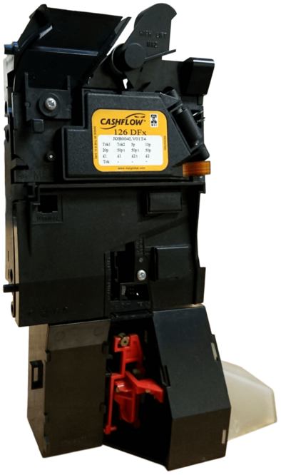
So I was thinking : "Could I connect it to the gpio pins of a raspberry pi ?".
Luckily I found some documentation/manuals on how to use this device.
You can find a small manual and a bigger manual on the internet.
Reading the manuals you get some idea on how the device works and how it can be connected.
However, you can't actually pinpoint how the device precisely works.
So I found myself discovering it on the basics of some trial and error.
That's why my discoveries could be quite useful for someone who also wants to try this model somehow.The most important thing is the Machine Connector description :
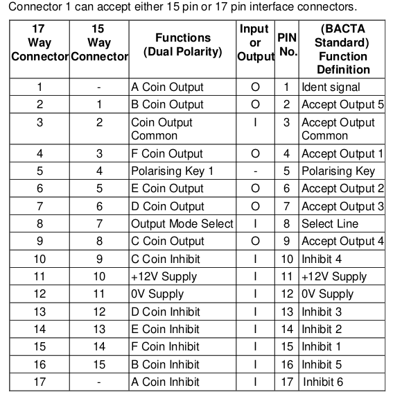
So I started with finding the supply pins.
My version has a 17 pins machine connector and in the manuals I found :- 0V on pin 12
- 12V on pin 11
So I connected a 12V 1500mA Switched-mode power supply adaptor.
From the manual a 2500mA supply is recommended but I didn't have it. (when I got it working the 1500mA seemed to do just fine)
The one I have is pre-programmed for euro coins and it particularly accepts 1 and 2 euro coins.
So I tried them and discovered that the coins were rejected.
I also noticed that a led started flashing 4 times.
From the manual I found that this means :- 4 Flashes -> Coin recognised but not accepted due to inhibit setting
What on earth does inhibit mean.
The manual says this about inhibit :Parallel Output mode inhibits = The channels that activate the associated coin output will be inhibited when the inhibit is held High, (e.g. Inhibit A will inhibit coin output A channels).Found the inhibit pins on both the "Machine connector" and the "Route inhibit" connector.
Which one to take ?First I had to find which route it is pre-configured with.
This is done with jumper wires on the "Routing plug".
Mine has the following wires connected :
- from pin 20(coin output F) to 6(Route 5(C))
- from pin 21(coin output G) to 5(Route 5(C))
(above description was wrong : pin numbering wasn't as assumed)This makes more sense :
- from pin 18(coin output D) to 2(Exit B)
- from pin 17(coin output C) to 3(Exit D)
So I figured I had to try one appropriate "Coin Inhibit pin from the Machine connector" and try to connect pin 10(C Coin Inhibit/Inhibit 4) to "high(?V)" of the "Machine connector".
High because the pin wasn't connected so I figured "low(0V)" would not work.
But what voltage to use as logical signals ?
My guess would be 5V because the device is from 1998 and 5V is very common for these days.
However I couldn't find it in the small manual.
After reading the bigger one I found eventually it in the bigger manual :Coin Inhibits - Input voltage to enable channels (logic 0) ) <1.0V - Input voltage to inhibit channels (logic 1) >4.0V - Input impedance 12 Kohms to +5vSo choosing "high" would mean that 5V should be enough.
I tried 5V on the pin with a 5V supply connecting :- 0V(12V supply) to 0V(5V supply)
- 5V on pin 10(C Coin Inhibit/Inhibit 4) to "high(?V)" of the "Machine connector"
So I tried both coins again and discovered that the coins were still rejected.
Mmmm, well if "high" doesn't work why not connect it to "low" :- 0V on pin 10(C Coin Inhibit/Inhibit 4) to "low" of the "Machine connector"
So I tried both coins again and discovered that one of the coins was accepted and routed to one of the acceptance routes.
I would have guessed that both coins should be accepted as they are both pre-configured to follow the "C" route.
So I figured : "Why not try to put the other inhibit input pins to "low" one by one." (on one I had success) :- 0V on pin 13(D Coin Inhibit/Inhibit 3) to "low" of the "Machine connector"
(above guess was wrong now that I know that the routing plug was read upside-down but it didn't matter because with testing the pins I figured it out anyway)
I found now that the other coin is also accepted and routed to one of the acceptance routes.
I would have guessed that both coins should be routed to the same route when accepted.
However for some reason one of the coins is re-routed to another acceptance route.
This is actually a nice thing as the coins can be separated in different locations.(above guess was wrong now that I know that the routing plug was read upside-down, the routes are pre-configured on the "Routing plug" as expected)
So now onto the next question.
Where to get the signal from when a coin has been inserted ?
I found that the device runs in parallel mode in default as stated in the manual :
A logic high signal to this pin will select parallel mode, setting pin 8 to a
logic low will select BCO mode. If there is no connection made to pin 8 the
interface will default to parallel mode.This means that for every coin some of the "X Coin Outputs" on the "Machine connector" will pulse "high(?V)".
With an oscilloscope I found the pins :- pin 7 D Coin Output/Accept Output 3
- pin 9 C Coin Output/Accept Output 4
Measuring it would reveal that :
- OV was floating revealing a noise signal on the oscilloscope
- the signal was about 3.3V (a straight line for about 100ms but Voltage was fluctuating from time to time)
I figured why not give it a try on the gpio pins.
In bash you can use this command to get the status of gpio 25 :
(make sure you have installed raspi-gpio with -> sudo apt install raspi-gpio)raspi-gpio get 25When nothing is connected it will output this :
GPIO 25: level=0 fsel=0 func=INPUT pull=DOWNThis is now the working command to check the gpio 24 and 25 and when it becomes "high" it will simulate a keypress with xdotool :
(make sure you have installed xdotool with -> sudo apt install xdotool)while true;do [[ $(raspi-gpio get 24) == *level=1* ]] && xdotool keydown 5 sleep 0.2 keyup 5;[[ $(raspi-gpio get 25) == *level=1* ]] && xdotool keydown 5 sleep 0.2 keyup 5 sleep 0.2 keydown 5 sleep 0.2 keyup 5;done(xdotool only works when using X, so from the CLI in a desktop environment)It was a bit risky connecting the output pins to the coin acceptor directly to the RPI, but I tried anyway.
It didn't work.
I checked my gpio pins again with a jumper-wire connecting 3.3V(on the RPI) to the gpio pins 24(on the RPI) and 25(on the RPI) temporarily.
Luckily both gpio pin were still good.My hunch was to read more about pin 3(Coin Output Common Line) in the manual which says :
Coin Output Common Line :
This line allows for operation with positive or negative common systems.
The interface self-configures by sensing the output common voltage
supplied by the machine on the coin output common line, (pin 2 for a 15
way machine interface connector, or pin 3 for a 17 way connector).
All potentials are relative to the 0 volt return line to the machine. pin 11 for
a 15 way connector and pin 12 for a 17 way machine interface connector.
Negative common operation is selected when pin 2 output common is 0
volts or negative with respect to pin 11.
Positive common is selected when pin 2 is more positive than +7 volts
with respect to pin 11.
So I figured putting 12V onto this line.
Re-measuring it with the oscilloscope gave this :- OV was floating revealing a noise signal on the oscilloscope
- the signal was approximately 5.4V (a straight line for about 100ms)
Well, 5V is too high for the RPI.
So I needed a voltage divider :(0V) ---2K---1K--- (5V)
xxxxxxxxx|
xxxxxxx(3.3V)Above voltage divider can be found on the internet.
However I didn't have these resistors and my pulse output was more than 5V.
So I came up with these dividers :
(the two 3.3K right resistors are placed in parallel making it 1.65K)
xxxxxxxxxxxxxxxxxx|---3.3K---|
(0V) ---2.2K---3.3K---|---3.3K---|--- (pin 9 C Coin Output/Accept Output 4)(pulse about 5.4V)
xxxxxxxxxxxxxxxxxx|
(RPI gpio 24)(pulse about 3V)
(the two 3.3K right resistors are placed in parallel making it 1.65K)
xxxxxxxxxxxxxxxxxxx|---3.3K---|
(0V) ---2.2K---3.3K---|---3.3K---|--- (pin 7 D Coin Output/Accept Output 3)(pulse about 5.4V)
xxxxxxxxxxxxxxxxxxx|
(RPI gpio 25)(pulse about 3V)Re-measuring it with the oscilloscope gave this :
- Ov was not floating anymore (a straight line)
- the signal was approximately 3V (a straight line for about 100ms)
So it was time to test it again.
Before testing also make sure that 0V/gnd of the RPI is connected to the 0V/gnd of the coin acceptor.
Lo and behold it WORKS !!!!!!.
So now it's possible to run emulationstation together with the detection line, from the CLI, like this :
emulationstation|while true;do [[ $(raspi-gpio get 24) == *level=1* ]] && xdotool keydown 5 sleep 0.2 keyup 5;[[ $(raspi-gpio get 25) == *level=1* ]] && xdotool keydown 5 sleep 0.2 keyup 5 sleep 0.2 keydown 5 sleep 0.2 keyup 5;doneThen go to the arcade section and use mame or derivatives that use pressing "5" to insert a coin.
The detection command will produce :- 1 credit with 1 euro
- 2 credits with 2 euro
The detection command will still be active when you quit emulationstation.
Then just press "ctrl_c" to get back in the CLI.Of-course, the detection line can somehow be implemented at the OS startup.
I hope this guide is a good and useful archive for anyone who want's to try the same.
New added information :
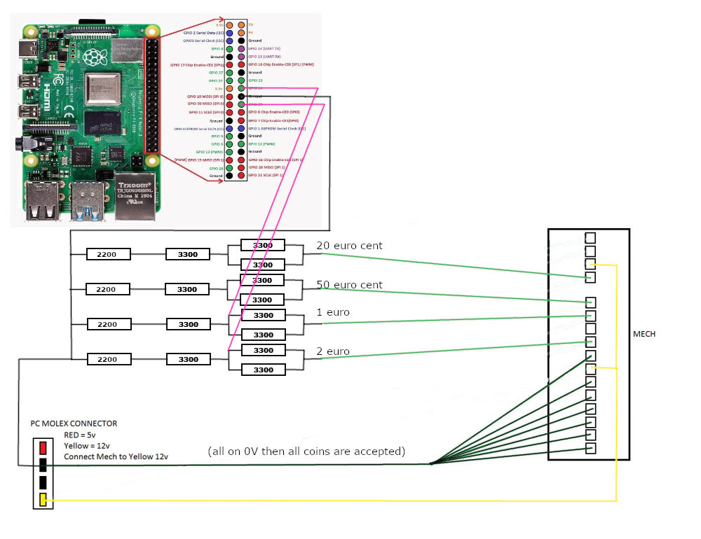
20 eurocent and 50 eurocent are also accepted, so summarised for all coins the connection are :- 0V on pin 15(F Coin/Inhibit/Inhibit 1) to "low" of the "Machine connector" and 20 eurocent is accepted and pulse will be on pin 4(F Coin Output/Accept Output 1)
- 0V on pin 14(E Coin Inhibit/Inhibit 2) to "low" of the "Machine connector" and 50 eurocent is accepted and pulse will be on pin 6(E Coin Output/Accept Output 2)
- 0V on pin 13(D Coin Inhibit/Inhibit 3) to "low" of the "Machine connector" and 1 euro is accepted and pulse will be on pin 7(D Coin Output/Accept Output 3)
- 0V on pin 10(C Coin Inhibit/Inhibit 4) to "low" of the "Machine connector" and 2 euro is accepted and pulse will be on pin 9(C Coin Output/Accept Output 4)
The device can also work when the "Routing plug" is removed.
If so, then all accepted coins will go out via one acceptance route.
Here is the basic connection schematic :
Here you will find info for making your own DIY coin acceptor version.
-
@Folly Nice reversing/hacking. Thanks for the write-up. Luckily you did not fry the Rpi's GPIO with too high voltage.
About the voltage divider: I guess you did not have MOSFETs lying around, but probably you know the level-shifting trick with those [1]. I have some cheap BSS138 in my drawer for those occasions.
[1] https://www.digikey.com/en/blog/logic-level-shifting-basics
-
Thanks.
Yes indeed I agree I could have used some other stuff though I only had resistors and level-shifters.
The disadvantage of the level shifters is that you have supply it with 3.3V and 5V which would mean 2 additional wires.
The other thing is that my level-shifters have 8 bi-directional ports and I only had to use 2 ports. So that's basically the reason why I didn't use it.The other solution could be to apply about 10V to the pin 3(Coin Output Common Line). But that also required some stuff.
Basically the resistors were the easiest thing for the moment.
Made a small case a around my pcb and fixed the wires with a tie-wrap.
I am quite happy now so I think I will keep it this way ;-)Now I should make an arcade cabinet, not sure I have time for that :-)
-
@Folly These kind of coin acceptors are popular in virtual fruit machines, there's alot of info on https://www.desertislandfruits.com/forum/index.php?/topic/13385-mei-9524e-coin-mech-setup-for-mfme/
-
Nice picture in the thread you mentioned.
Although not directly suitable for the connections to the pi.
Will have a look if I can use and change the picture to display how I connected it to the pi like described in post 1.Edit:
I have added the basic connection schematic to post 1. -
@Folly Great work! Lovely bit of tinkering!
-
Nice to hear that you like it, thanks.
If you want, then you can just use the code and connect the gpio 24 and 25 via 2 push buttons to 3.3V on the pi.
It will then simulate the coin device.
Like this :
/=push button
3.3V----/ -----gpio 24
3.3V----/ -----gpio 25With above you would also be able to make a DIY coin acceptor.
Just inserting a coin through a selfmade coin-route that has just a switch. So that the coin will enable the switch temporarily. -
Discovered that
xdotoolneeds X to run properly, go figure.So for the normal Retropie without X(Desktop OS) another solution has to be made.
-
@Folly said in Cashflow-126 coin acceptor to RPI gpio pins guide:
Discovered that
xdotoolneeds X to run properly, go figure.So for the normal Retropie without X(Desktop OS) another solution has to be made.
A solution to this problem could be to make use of
ydotool.
To use this program you have to install ydotoold and ydotool from source like described on this page :
https://gabrielstaples.com/ydotool-tutorial/#gsc.tab=0
(the packages from the repository seem to be too old and are not work correctly , when installing with : sudo apt install ydotoold ydotool ,
if already installed then remove the packages first with : sudo apt purge ydotoold ydotool)To use
ydotool,ydotooldserver has to be running using this command :
To execute the output just do something like this :sudo -b ydotoold --socket-path="$HOME/.ydotool_socket" --socket-own="$(id -u):$(id -g)"
Press enter when it says ready after that the server is running.
Then we can startemulationstationtogether withydotoollike this :emulationstation|while true;do [[ $(raspi-gpio get 24) == *level=1* ]] && YDOTOOL_SOCKET="$HOME/.ydotool_socket" ydotool key 6:1 -d 200 6:0 -d 200;[[ $(raspi-gpio get 25) == *level=1* ]] && YDOTOOL_SOCKET="$HOME/.ydotool_socket" ydotool key 6:1 -d 200 6:0 -d 200 key 6:1 -d 200 6:0 -d 200;done
(it will press "5" or "55")After some tests
ydotoolalso seems to work only from within a linux setup with desktop environment.
Too bad as it supposed to work from a linux cli without using desktop.
Also tested the command using theevalcommand still same result.More tests reveal that
ydotoolis working now when using it with a setup without desktop environment but for now it will only work when using a RetroArch core like lr-mame. :-)For standalone MAME above, using "5" will however only work when using it on a setup with desktop environment.
In standaline MAME I discovered that
ydotooldis detected as a ydotoold virtual device looks like it's detected as joystick.
By trial and error I discovered the joy 1 back btn code.
Here mouse click examples can be found which uses 0xC1.
So I tested other codes and opened MAME gui to edit the button for coin 1.
0xC3 was the code for joy 1 back.
0xC4,0xC5,0XC6 are alse joy buttons If I remember correctly, they are in the same range.
So to getydotoolworking when using it with a setup without desktop environment and standalone MAME the command has to be :
(using only the 1 euro option)
emulationstation|while true;do [[ $(raspi-gpio get 24) == level=1 ]] && YDOTOOL_SOCKET="$HOME/.ydotool_socket" ydotool click 0xC3;doneHoped that this command would also work for lr-mame but that doesn't seem to be the case.
But for now both options seem to work fine.Edit :
Ydotool RetroArch autoconfig added over here :
https://github.com/FollyMaddy/RetroPie-Share/blob/main/00-retroarch-00/retroarch-joypad-autoconfig/ydotool_virtual_device.cfg -
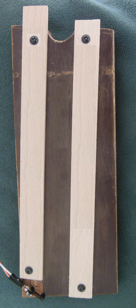
Today I had time to make a simple DIY coin-acceptor.
It's just a simple test setup using :
- a wooden plank
- 2 paint stirrers
- a simple switch
- a few screws
- 2 jumper headers
- 2 jumper wires
- 1 euro coin
The created "open" slide setup :
Using a simple switch :
No resistors are needed as gpio uses a pull-down resistor by default, see here :pi@raspberrypi:~ $ raspi-gpio get 24 GPIO 24: level=0 fsel=0 func=INPUT pull=DOWN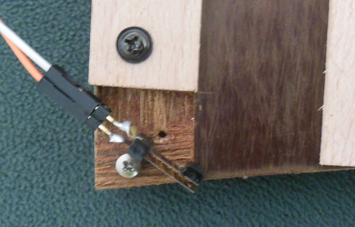
Orange connected to 3.3 Volt and white connected to gpio 24 :
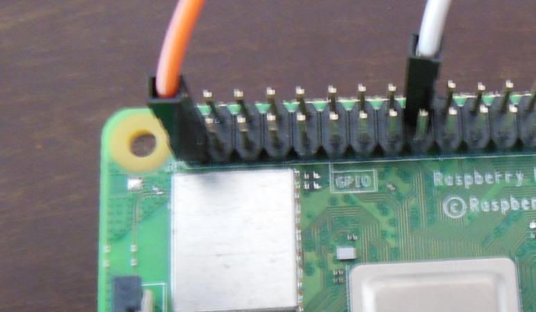
The same commands can be used as used with the Cashflow-126 coin acceptor and can be found over over here.
-
 F Folly referenced this topic on
-
Just tested if this project can be combined with LEDSpicer like this over here :
Syncing button leds with gameplayIt works !
But be aware of the danger, do not use the GPIO 24 and 25 in LEDSpicer when using both projects together.
Contributions to the project are always appreciated, so if you would like to support us with a donation you can do so here.
Hosting provided by Mythic-Beasts. See the Hosting Information page for more information.