NC/NO Power Switch Setup
-
RPi 3 B+
RPi Official 12.5w Power Supply
RetroPie v4.8Hey guys, looking to see if I can get some (I'm hoping ) simple help. I'm not an electrical engineer, so some of this stuff goes over my head, but I'm mechanical, so I can grasp some.
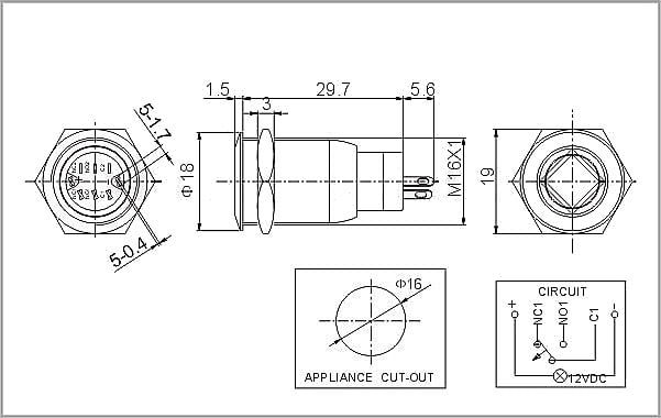
Trying to set up an NC/NO switch for power with an LED. I'll add photos of the switch and the legs. Every go-by I seem to come across is using different switches, almost always momentary, and I'm not proficient enough to translate that into the switch I have.
I'm also unsure of the code used to turn the system on/off and if me running RetroPie has any different bearing on that, hopefully someone can help with that.
Also, do I need a resistor inline with the led on the switch?
Thank in advance.

-
@glassmonolith There are literally hundreds of walk-throughs on how to setup a power switch online. Have you googled the switch part number and raspberrypi and see what comes up?
-
There are literally hundreds of walk-throughs on how to setup a power switch online.
Every go-by I seem to come across is using different switches, almost always momentary, and I'm not proficient enough to translate that to the switch I have.
There is no part number, only Adafruit's product ids, and I'm still unable to find a result showing the setup of specifically an nc/no switch with an led. Not to say it isn't out there, just that 1: I haven't been able to find one yet, and 2: I can ask questions in a forum to ensure I know what I'm setting up. I haven't had much luck asking my computer screen questions yet, which is why a forum felt more viable.
(I did however just find out that a resistor is built in, so redact that question).
I also realize I forgot to add the details of the product and photos that will be viable for someone looking to help. I'll add those now.
-
@glassmonolith That looks to me like whats called a momentary switch, so check out this as a start:
https://howchoo.com/g/mwnlytk3zmm/how-to-add-a-power-button-to-your-raspberry-pi -
It is not a momentary switch. It is an NC/NO switch (maybe I'm not calling it by it's correct name). It is a switch that STAYS in an on or off position.
Again, every go-by I find is for a momentary switch and I am not proficient enough to know how to alter that info for a working nc/no with an led, or if the process is even different. Would the setup still be the same?
-
@glassmonolith said in NC/NO Power Switch Setup:
It is an NC/NO switch
Momentary switches can often times also do NO or NC (depending on how you wire them). The diagram in your first post seems to indicate this is a momentary switch. Does it hold it's position when pressed? Then it's a latching switch.
How are you connecting this to your Pi? Are you trying to make it do a safe shutdown upon powering off?
If not, and you just want to have a latching switch kill the power to the Pi, you could wire it into the power supply's lead. But that doesn't give you a safe shutdown, which introduces a risk of data corruption.
-
Ahh okay, so "latching". It is a latching switch. It stays in on/off positions when pressed. I'm trying to get it to work as such (so on when it's pressed in, off when it's out). I definitely would like a safe shutdown process, so I'll be wiring it up to the header pins.
-
So is this something that's easy to achieve?
It's latching, so I'm looking to have the two way action work in a manner that does this;
1: Push in:
-
powers on the Pi (assumedly ES and Retro start up as they should)
-
powers on my fan
-
powers on the led
2: Push again to disengage latch:
-
powers down ES/Retro so I have a safe shut-down
-
powers off my fan
-
powers off the led
-
powers off the Pi?
-
-
@glassmonolith I might not be too knowledgable about all the possibilities, but I imagine that turning off a latching switch while also triggering a safe shutdown would be quite difficult. After all, the switch just immediately kills the power upon 'unlatching', while a safe shutdown needs a little software script to be triggered and run first, before killing power.
I have my cab (also running a Pi 3B+) wired with one of these ubiquitous kettle plug things:

But that's just for providing power to the Pi, screen, audio and lights. Everything turns on as expected when switched to the 'I' position, but when turning it off, I first use a separate pushbutton (wired up to some GPIO pins) to run a shutdown script on the Pi. Only after the shutdown finishes, I switch the kettle plug off to 'O', effectively killing all power to the cab.
-
@glassmonolith your approach needs a second circuit and logic outside the Pi. Although you might be able to physically disconnect the mains (via a relay switch) you would have to detect when the Pi is shut down to disconnect the mains. And the extra circuit with your proposed button will have to be powered all the time to start your Arcade again.
I also use a rocker switch with an separate IEC C13/C14 inlet, similar to what @WeirdH uses. But I don't use an extra shutdown ES via GPIO logic. I do the combo: Start P1 (for Main Menu), then Trigger Right (Last Entry = Quit), then A, then Trigger Right (Last Entry = Shutdown System), then A. Additionally If you add
--no-confirm-quittoautostart.shit saves you to press A once more (on the confirm dialog). :) -
Okay. See that's where my lack of knowledge becomes difficult/dangerous. I was hoping that the GPIO logic would be able to simply read the difference between two pins being (shorted?) or not and code would have been able to just assign parameters to what to control in each circumstance without all the extra circuitry.
Hmmm.
Contributions to the project are always appreciated, so if you would like to support us with a donation you can do so here.
Hosting provided by Mythic-Beasts. See the Hosting Information page for more information.