Pi in a Sega Genesis USB Hub Build
-
@meyemind
Sad the mausberries are out of stock.Maybe @obsidianspider can help with questions how to solder the audio Adapter. It works if you use headphones vor external amp
-
@cyperghost said in Pi in a Sega Genesis USB Hub Build:
Maybe @obsidianspider can help with questions how to solder the audio Adapter. It works if you use headphones vor external amp
I don't have a volume slider on my build. I just have a hole in the back of the case to allow the Pi's composite/audio out to come through. That said, I can try to give advice to @meyemind, but I'm not sure what your goal is for the slider.
Unrelated to volume sliders: If the post office tracking is to be believed, my power switches should be here this afternoon, so I should have all of the parts to put my project together. (I think this is still my build thread. ;) ) Then the trick will be to find time over the busy next few days to actually do it.
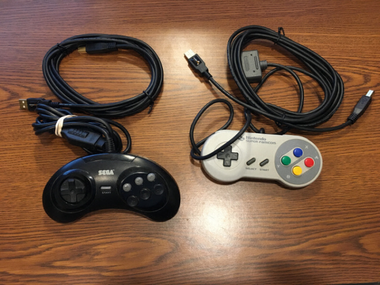
I also ordered two Raphnet adapters to convert the Super Famicom and Sega Genesis controllers I bought on eBay to USB. Those adapters should be here in a little while, but Raphnet are closed the last week of December, so we'll see if I beat the shipping deadline. While not directly RetroPie-related, I think I'll write up how I mod those controllers in a separate post.
-
@obsidianspider said in Pi in a Sega Genesis USB Hub Build:
I don't have a volume slider on my build. I just have a hole in the back of the case to allow the Pi's composite/audio out to come through. That said, I can try to give advice to @meyemind, but I'm not sure what your goal is for the slider.
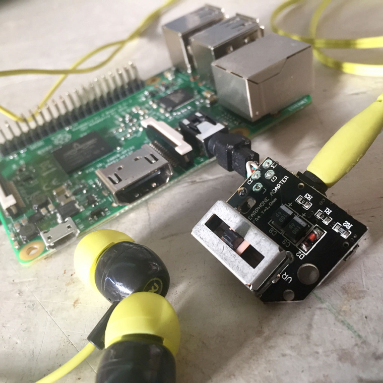
Hi gents ( @obsidianspider, @antricluc, @cyperghost ), ya my new goal (which avoids a more complicated ADC setup) is to mount the PS4 Slider under the USB volume slider like on the original Sega Genesis and have it only operate the volume if headphones are plugged in, which is still a nice feature right? Then we'd get proper use out of it :) I've tested it between the pi3's jack and and it works fine, but I'm going to have to figure out a couple of more things:
-
How to wire this headphone jack to the pi3's, because obviously the pi3's jack will be facing outside so if someone knows how to wire the PS4 volume slider's jack through to the pi3 board's jack, please let me know how I can do this.
-
How to get the feature of sound to toggle between the HDMI and Headphone Jack depending on if a jack is plugged in or not, right now via Retropie's OS for example, you can switch between 'either' HDMI or the HP Jack... but it won't work auto or dynamically, again, if my headphones ARE NOT plugged in, I'm getting sound via HDMI through my TV, but once I plug in my headphones in, NO sound coming from the TV but now be it's in my headphones.
Thanks in advance!
-
-
@meyemind AWESOME. I'm waiting for my switches and still waiting on mausberry stock. Gonna start cutting out HDMI and micro USB port with my needle files.
-
Is there a way to wire the hub directly to the pi zero gpio? Or is it best to just run it from USB? The cord is pretty long.
-
@antricluc I'm not using a Zero, but you can solder wires from the hub to the test pads on the bottom of a Zero. I didn't use the USB cable that came with the hub.
-
@obsidianspider I have to apologize, I'll start a thread and move things over to it later tonight. I got excited and wanted to follow your work, but I'm making it a sh*t storm of confusion, good luck with the build I will be following it closely :)
-
@meyemind It's OK to post here, it's certainly not my website, but it can get confusing with multiple concurrent builds going
on. I'm eager to see what you come up with regarding the volume slider. -
I'm interested in all your work. It's cool I'm not the only one that had the idea. Surely please both post what you guys can to help each other out. We seem to all have the same idea. Definitely would love to add a volume slider but not really necessary but power switch is a must. Can't really get that done till mausberry has a resupply.
-
The mail carrier came and went. No switches today. Hopefully they show up tomorrow or Saturday so I have time to fuss with this and get it "done" on the long weekend.
-
@obsidianspider @antricluc i am not going to do a build thread so i am posting this to help you guys. you need a small enough slide switch for it to work like this. first super glue your switch to the switch cover like this. 2 sides and the top can be super glued for maximum strength. you need to make sure the switch is glued on this side so you have room for the slider potentiometer for the volume

next screw the switch cover back in and hot glue the switch like this. use the plastic on the underside of the reset button as a guide to make the switch straight. luckily the 2 "guide posts" that the switch is sitting on top of make the switch sit flat

-
@edmaul69 Nicely done. I'm thinking about also putting a piece of plastic between the switch slider and the edge of the case slider, so the switch itself has less chance of moving.
-
@obsidianspider are you saying on the back of the fake power switch making a "wedge" to keep the black plastic of the real switch in place to keep it from breaking loose? if that is the case then i wouldnt even super glue them together. that way if your switch breaks you dont have to try to get the 2 pieces seperated.
-
@edmaul69 Yeah, I think we're on the same page there. I have to see just how big the switch is in the case and how things are oriented when the switch is open vs closed. I don't anticipate me using the slider, but if I can keep it from looking ugly, I'd prefer that route.
-
@obsidianspider so far lookin good. How do you plan on connecting the switch? Mausberry?
-
@edmaul69 Nice one, I was shaving down the plastic switch to fit inside that small circle, but this layout seems to a much better approach!
Is that a 3 position switch? I think I'm going to pick up the SPST's @obsidianspider is using instead. The 3 position switches I picked up and posted above are not ideal for this project.
-
@edmaul69 Heya, do you have a link to that switch you are using, with the pins down and the switch on the side? huh, I'm confused. :)
-
@obsidianspider
Oh I related my posting in that way that you can give the connection pad numbers to @meyemind ... I am in journey and I do not have a Pie there. Because I knew the question "how to connect the audio volume spider to the Pie" would be asked.@meyemind
You asked for an automatic switch from HDMI to analog audio?
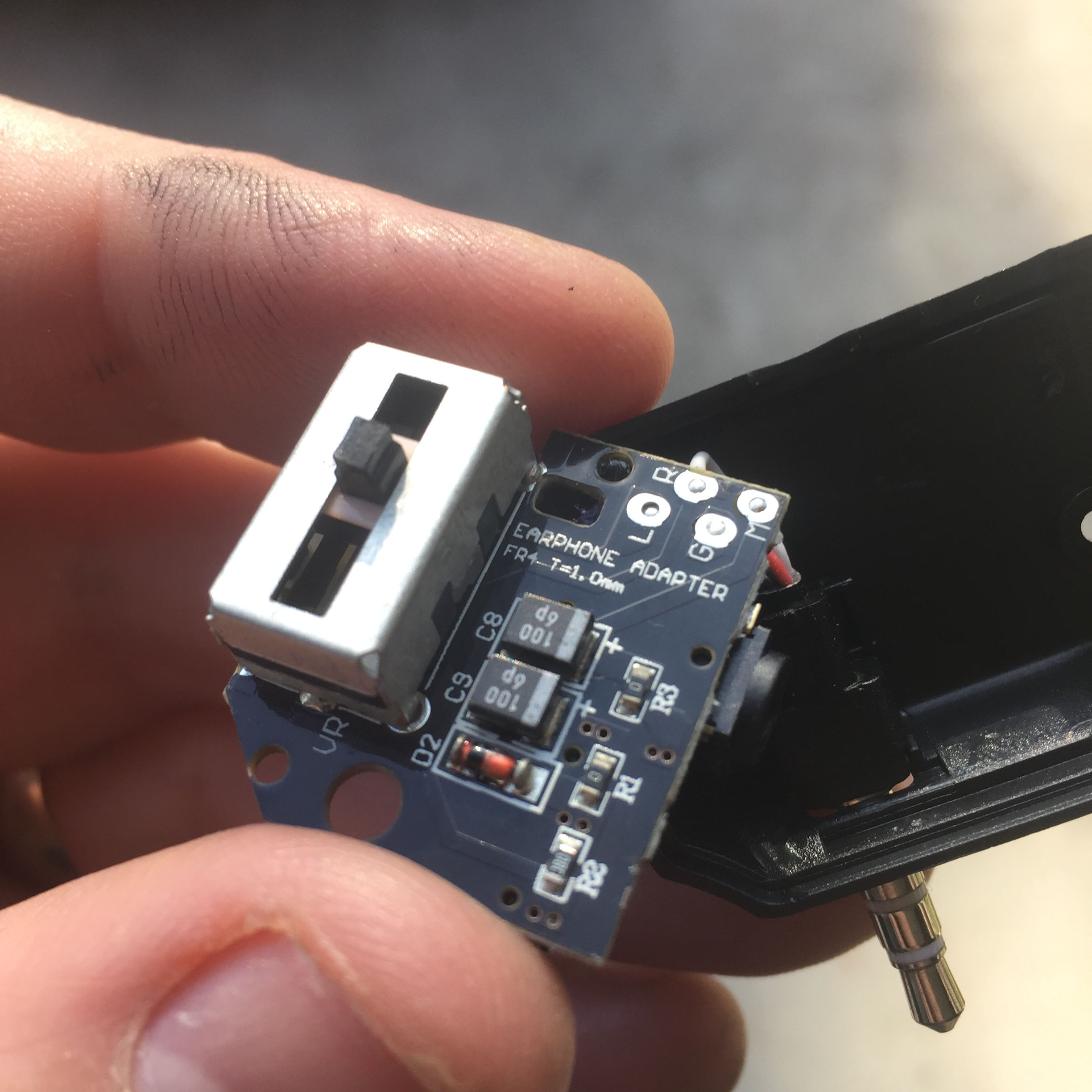
There are audio connectors with an internal switch. They are used to mute external amps and give audio through headphones. You can use that switch to give signal to GPIO and then you can run a script to change audio source.I think it is a amixer command 'amixer 1' or something this way. Please use Google for that. That should works. About the audio connector .... For stereo there exits several connector (3 wires) with a switch but if you like to use also Video output you need a special connector with 4 wires.
-
@meyemind. my buddy ordered the switches so i have to get the info from him tonight when he gets home. it is a 2 position switch. for an on off switch you only solder a wire to the middle and the on side.
-
@hansolo77 i am not using a mausberry so i am just going to wire the 5v wire from the hub directly onto the power switch. I did that with my nes cart.
Contributions to the project are always appreciated, so if you would like to support us with a donation you can do so here.
Hosting provided by Mythic-Beasts. See the Hosting Information page for more information.