Pi in a Sega Genesis USB Hub Build
-
I'm interested in all your work. It's cool I'm not the only one that had the idea. Surely please both post what you guys can to help each other out. We seem to all have the same idea. Definitely would love to add a volume slider but not really necessary but power switch is a must. Can't really get that done till mausberry has a resupply.
-
The mail carrier came and went. No switches today. Hopefully they show up tomorrow or Saturday so I have time to fuss with this and get it "done" on the long weekend.
-
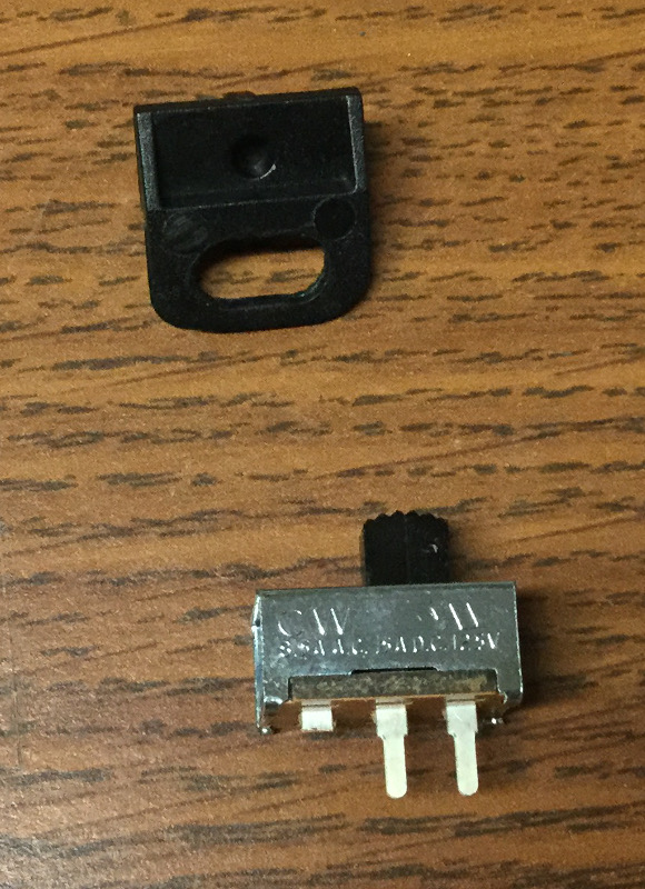
@obsidianspider @antricluc i am not going to do a build thread so i am posting this to help you guys. you need a small enough slide switch for it to work like this. first super glue your switch to the switch cover like this. 2 sides and the top can be super glued for maximum strength. you need to make sure the switch is glued on this side so you have room for the slider potentiometer for the volume

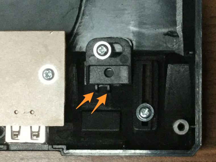
next screw the switch cover back in and hot glue the switch like this. use the plastic on the underside of the reset button as a guide to make the switch straight. luckily the 2 "guide posts" that the switch is sitting on top of make the switch sit flat

-
@edmaul69 Nicely done. I'm thinking about also putting a piece of plastic between the switch slider and the edge of the case slider, so the switch itself has less chance of moving.
-
@obsidianspider are you saying on the back of the fake power switch making a "wedge" to keep the black plastic of the real switch in place to keep it from breaking loose? if that is the case then i wouldnt even super glue them together. that way if your switch breaks you dont have to try to get the 2 pieces seperated.
-
@edmaul69 Yeah, I think we're on the same page there. I have to see just how big the switch is in the case and how things are oriented when the switch is open vs closed. I don't anticipate me using the slider, but if I can keep it from looking ugly, I'd prefer that route.
-
@obsidianspider so far lookin good. How do you plan on connecting the switch? Mausberry?
-
@edmaul69 Nice one, I was shaving down the plastic switch to fit inside that small circle, but this layout seems to a much better approach!
Is that a 3 position switch? I think I'm going to pick up the SPST's @obsidianspider is using instead. The 3 position switches I picked up and posted above are not ideal for this project.
-
@edmaul69 Heya, do you have a link to that switch you are using, with the pins down and the switch on the side? huh, I'm confused. :)
-
@obsidianspider
Oh I related my posting in that way that you can give the connection pad numbers to @meyemind ... I am in journey and I do not have a Pie there. Because I knew the question "how to connect the audio volume spider to the Pie" would be asked.@meyemind
You asked for an automatic switch from HDMI to analog audio?
There are audio connectors with an internal switch. They are used to mute external amps and give audio through headphones. You can use that switch to give signal to GPIO and then you can run a script to change audio source.I think it is a amixer command 'amixer 1' or something this way. Please use Google for that. That should works. About the audio connector .... For stereo there exits several connector (3 wires) with a switch but if you like to use also Video output you need a special connector with 4 wires.
-
@meyemind. my buddy ordered the switches so i have to get the info from him tonight when he gets home. it is a 2 position switch. for an on off switch you only solder a wire to the middle and the on side.
-
@hansolo77 i am not using a mausberry so i am just going to wire the 5v wire from the hub directly onto the power switch. I did that with my nes cart.
-
@meyemind @obsidianspider here is a link to the switches i bought if it helps you any. It is a 10 pack for cheap
switches link -
@edmaul69 Thanks you kindly, these look like they will work out well!
-
@cyperghost Thank you for the insight regarding the audio jack w/ a switch, that sounds like a great plan and a bummer that the PS4 slider won't work out (even though the lineup of the volume slider and the jack pretty much worked for this usb case!! :) I'm going to look at picking up a pot and 3.5 w/ switch online today, thank you again.
-
Even though my power switch seems to be floating around in the mail system, I decided to get everything else done on the build this morning.
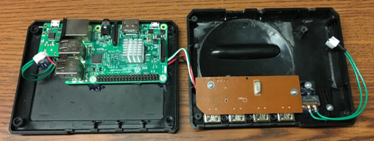
I removed the "In" and "Out" pins as well as the spring header from from the Mausberry. I then soldered the power out to the lines on the Pi's micro USB test pads and soldered some 28 AWG wires to the GPIO pins for the Mausberry's soft shutdown to function. I used 22 AWG wire for the switch lines. That's most certainly overkill as I'm pretty sure that's just a trigger wire, but once everything was connected I put some hot glue on the solder points for strain relief.
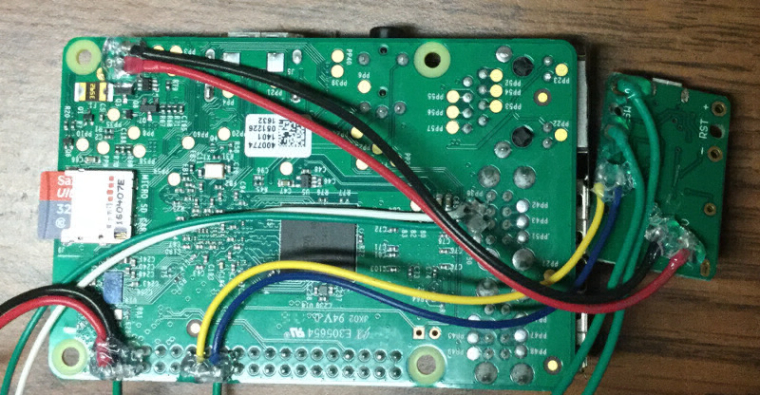
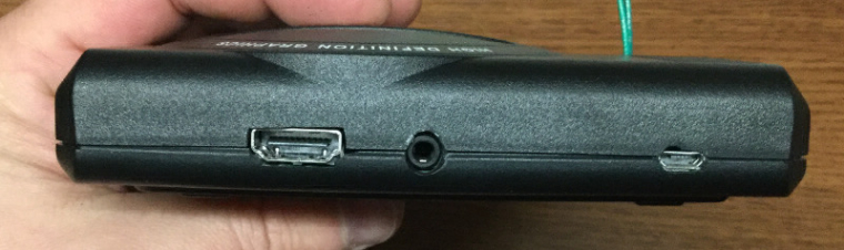
I filed the existing power hole to allow the micro USB power port to fit. The round hole is a bit too tall, but you can't exactly put plastic back that was never there to begin with. It's not perfect, but it works.
Since the Mausberry's mounting holes are on the side where there is a ridge inside the case I decided to just use the pressure of the case to keep the outside in place and to glue a riser with a stud in the back so when you insert the micro USB cable the Mausberry has a something to back into so it won't move.
I rerouted the USB connection to the top of the board, securing those solder points with some hot glue for strain relief and then screwed everything in place.
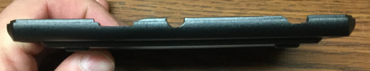
There's a slight bulge in the middle of the case, but I think that's from the power wire on the bottom, not the heatsink (I guess I'll find out if something melts) but it's not too bad, and it's in the back.
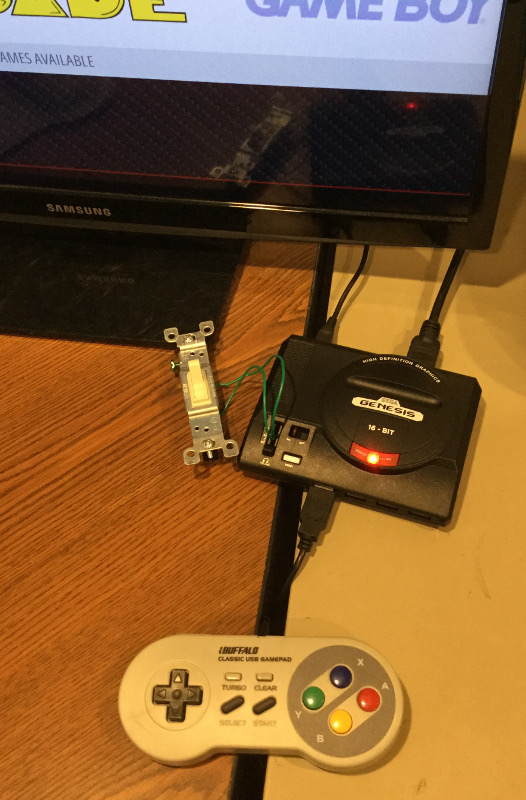
Until my real power switch shows up I'm just using a spare light switch to control the Mausberry. It's utilitarian, but it works.
-
Why did you remove the spring headers and the in/out pins on the Mausberry? Was it because of case clearance, or did it just make the permanent attachment of the wires easier that way? Other than that, looks good. Can't wait to see how you work the power switch.
-
@hansolo77 I removed the pins for in/out because they were really close to the USB and Ethernet housing, and to be honest, I didn't want a bunch of wires flopping all over. I chose to solder the power wires because I know Pi3 can be finicky with power, so I wanted a solid connection, plus it looks cleaner.
Clearance wa not an issue in either case, but I did put some electrical tape over the Ethernet port because of soldering the switch wires and the connection being a little close for comfort.
I just hope my switch actually shows up! ;)
-
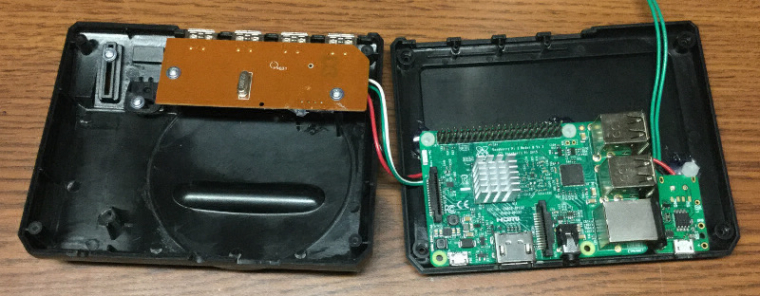
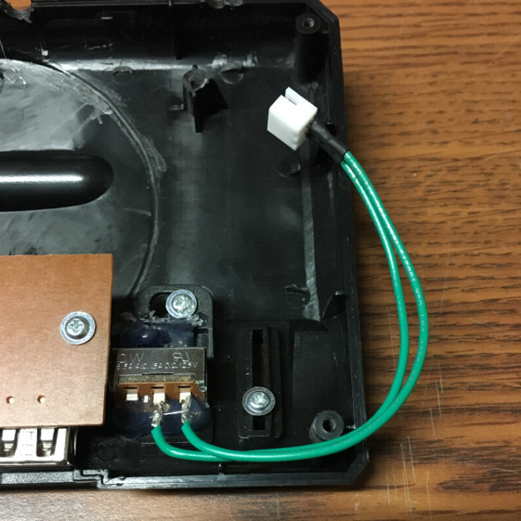
My switch arrived Tuesday and I was able to get my build complete on my lunch break today.
The switch I ordered was a very good fit size-wise for the Genesis USB hub's slider.
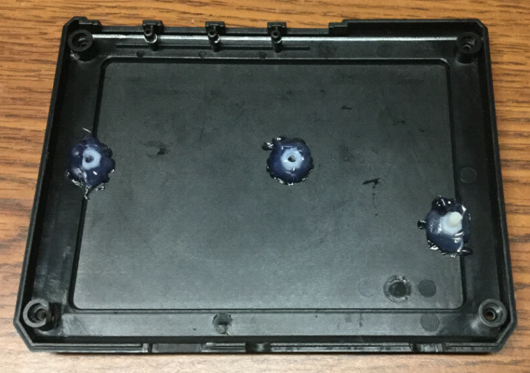
In order for the switch to fit the case I had to remove half of the nubs that the lock the slider in place. I did this with an xacto knife.
I used hot glue to secure the switch to the slider first, then I soldered the power wires to the switch, then I glued the switch to the case. I had to trim a bit of the glue as it caused some binding with the slider, but overall it seemed to turn out pretty well. I chose to use a JST connector to make taking the case apart manageable in case I want to swap out the SD card or if something breaks. I'm not sure how durable the hot glue will be, but with quite a few on-off cycles, it seems to work pretty well.
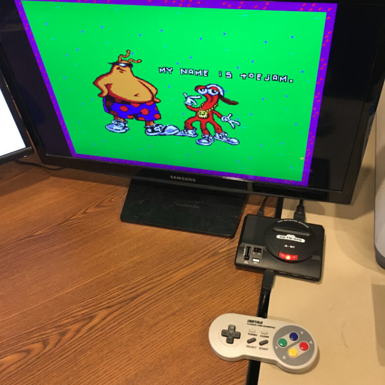
It's about time that I actually finished at least one build that I started this year.
-
@obsidianspider awesome job. Awaiting my switches. Quick question. It seems you don't have the mausberry USB plugged in. Did you just solder the pads directly due to it wouldn't fit other wise? I have the zero, would this same setup work with the zero as well? Mausberry just got restock and I'm going to make a purchase but want to make sure I'm getting what I need
Contributions to the project are always appreciated, so if you would like to support us with a donation you can do so here.
Hosting provided by Mythic-Beasts. See the Hosting Information page for more information.