Help needed for a Handheld Project
-
@moosepr Brilliant, thank you so much. So basically, in my handheld I'll be cutting squares from the PCB to mount buttons on them. Then connect all the ground pins with wires all going into one wire connected to the ground?
How do I connect the analog stick? In the OP I got a Wii U analog stick which already seems to have a PCB. It has 4 pins, I'm thinking it uses Red, Black, Yellow, and White wires, how do I connect those?
-
@Jiehfeng your analog stick seems to have 5 pins. They normally work like variable resistors, which have 3 pins. One will be connected to +ve, one to -ve, and the this is connected somewhere in between. Your teensy will measure the voltage from the middle pin, which will change depending on it angle of the stick.
https://www.arduino.cc/en/Tutorial/AnalogInput
You will basically have 1 analog input for each stick direction.
-
want to get a tft into your project, look no further than here https://retropie.org.uk/forum/topic/7464/ili9341-tft-screen-guide
-
@moosepr What is +ve or -ve? Or where is that?

So to put it in perspective, what colour wires do I wire exactly from the 5 pins to the Teensy LC? (kinda noob so don't understand yet)
-
@Jiehfeng That arduino tutorial has many different parts I don't have, so I don't really know how to understand it with my own parts.
-
@Jiehfeng ah sorry, on the sticks, +ve is the pwr and -ve is the gnd. Connecting to the teensy you will want to connect the pwr pin on the stick to the 3.3v on the teensy, and gnd to gnd.
you will then want to connect the dir pins (dirH and dirV), into analog pins on the teensy (they are the a0-a9 pins). and for a final bonus, you could attach the click pin from the sticks into any of the digital pins (the grey ones on the diagram) you could always assign them to start/select so you dont need the extra buttons
your code on the teensy will then read the voltage from the analog pins, which will range from 0 to 3.3v over the range of movement of the stick
want to get a tft into your project, look no further than here https://retropie.org.uk/forum/topic/7464/ili9341-tft-screen-guide
-
@moosepr Thanks a bunch, that's 90% of the info I need to finish my project. The other 10% is the wires. I understand completely where the pins connect to the teensy, but what colour wires for what pins?
GND - Black
PWR - Red
Dir H - Yellow?
Dir V - Green?
Click - White?Do buttons use red or white wire?
-
@Jiehfeng technically speaking, the colour of the wires is irrelevant. as long as you know what colour does what, your golden. Most people do tend to stick with red for power, and black for ground, but nothing is set in stone
-
Hey, I just got the Teensy LC with a few momentary push button switches. I put a button onto the PCB and soldered it on, then put a red wire to the top left pin and the black wire to the bottom left pin (soldered), and connected the black to the GND on the Teensy and the red to the 0 digital pin.
But for some reason my button isn't working? I tried the basic example and button example on teensyduino but the button won't respond. -
@Jiehfeng do you have access to a multimeter?
On the push buttons, there are normally 4 pins, but some are connected and some switch.
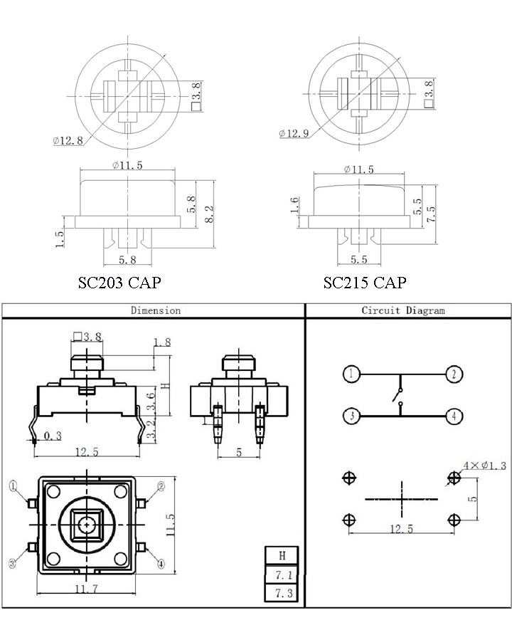
If you look at the bottom right part of the image, the top 2 pins are always connected together, and the bottom pins are connected together, then all 4 are connected together when the button is pressed
want to get a tft into your project, look no further than here https://retropie.org.uk/forum/topic/7464/ili9341-tft-screen-guide
-
@moosepr No sadly not.
I'll try switching the wires up to every possible pin and see if it works. The switch is SPST btw. -
@Jiehfeng Just tried with another button, works fine. I guess that button was faulty. Thanks again. :)

Contributions to the project are always appreciated, so if you would like to support us with a donation you can do so here.
Hosting provided by Mythic-Beasts. See the Hosting Information page for more information.