Solved: Setting up Gamecon driver with psx controller
-
From what I understand, you will need the resistor no matter which pad # you plug into. I use a 4.7k ohm resistor between 3.3V and the "Data" line, as well, and everything works great for me.
Can we get a picture of your setup?
-
@Katemonster Yeah I'll snap a pic tonight after work
-
Hi there,
I have almost the same problem. Using Rpi3 (with controlblock) and trying to connect a PS2 controller to the GPIO.
Connected as follows:RPI:------------------------PS2
P1-01 (3.3V) ==== 5 (power/3.3V)
GPIO14 ---> 2 (command)
GPIO15 ---> 6 (select)
GPIO18 ---> 7 (clock)
GPIO02 <--- 1 (data)
P1-06 (GND) ==== 4 (ground)see GPIO numbers GPIOs
Here is a pic from my setup:

I can configure the driver to PSX Controller, that is working fine, but when i test the controller, no input is registered.
I also tried my N64 controller some time ago (its the same driver) and got no signal either.
Someone any Idea how to fix that?
-
@Jeddo First off, I don't see pull-up resistors in that picture. Are there some integrated into the controlblock? I don't know anything about how that thing functions.
Secondly, try removing the controlblock from the equation, and hook directly to the Pi. What happens? Also, test the controllers and make sure the analog light comes on when pressed. If not, likely you don't have the power and ground hooked up properly. My problem was always that I counted the pins on the controller backwards. If it's not powering on, that could be the cause.
-
@Katemonster the controlblock should not affect the gpio. It's working for the db9_gpio_rpi driver without any problems. But I will check it without it.
Regarding the pullups: I always assumed that I don't need those because RPi 3 has internal ones on every pin?! Maybe that's wrong and I need the pullups.
Controller has power so that is working. -
Yes you need the pull ups. The driver doesn't try to use any internal pull up resistors because the internal ones are not powerful enough to sway the PSX bus.
-
@Katemonster ok thanks that could explain why my N64 controller isnt working, too. I will try that. Thank you for your help!
-
I don't know how the N64 controller works. I can only speak for the PSX controller, which needs the pull-up resistors.
-
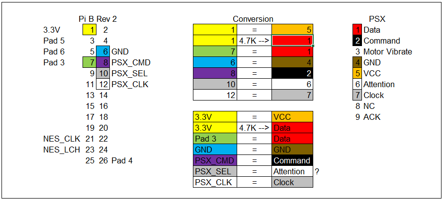
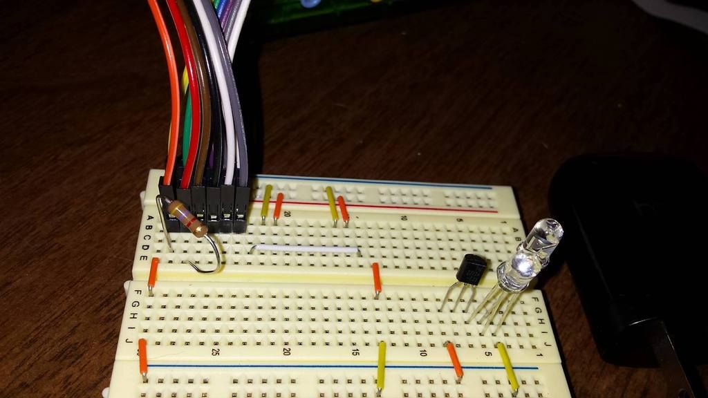
@Katemonster Here are some pictures that hopefully help show what I'm working with. I had to start fresh with a new image sorry for the delay, building from source takes a while.
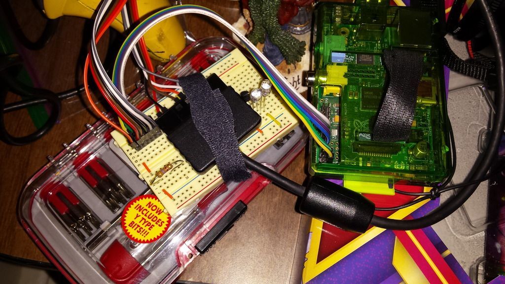
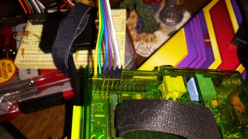
Hopefully this makes it a little more clearer.
-
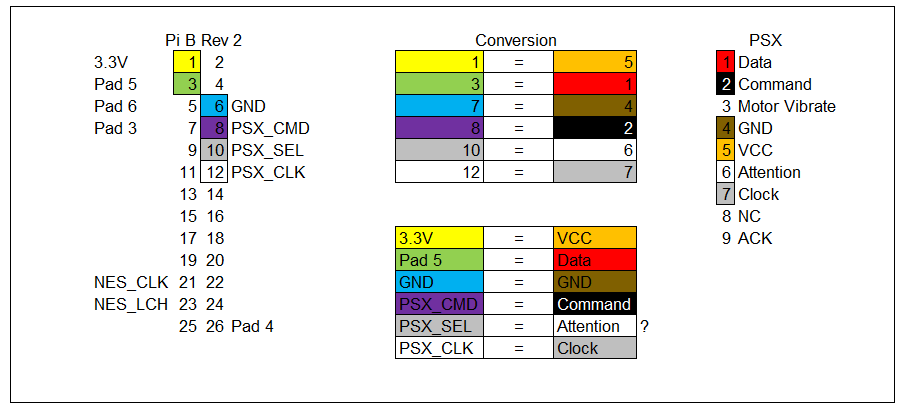
Thanks for the diagrams. In the last picture, what you've indicated as Pad 5 and 6 is actually Pad 1 & 2, respectively. So initialize the driver with map=7,0,0,0,0,0 and try again. If that doesn't work, try Pad 3 and use map=0,0,7,0,0,0 .
-
@Katemonster Oh I thought pads 1 and 2 changed to pads 5 and 6 from Model b rev2 and beyond.
from the link (https://github.com/retropie/retropie-setup/wiki/GPIO-Modules#gamecon_gpio_rpi) above I saw
"NES/SNES Controller Data Pin Location Legend
Rev01 board (Raspberry Pi B)
Gamepad1 = GPIO0 = Physical Pin03
Gamepad2 = GPIO1 = Physical Pin05
Gamepad3 = GPIO4 = Physical Pin07
Gamepad4 = GPIO7 = Physical Pin26Rev02 board (Raspberry Pi A, B+, 2, 3)
Gamepad3 = GPIO4 = Physical Pin07
Gamepad4 = GPIO7 = Physical Pin26
Gamepad5 = GPIO2 = Physical Pin03
Gamepad6 = GPIO3 = Physical Pin05
"I can try to swap that out for sure. I have a pull up resistor I can try it with.
Do you think it would be useful if in the RetroPie-Setup file I configured it for 2 NES/SNES controller then changes the options for what I need?
Is there any other configuration I need to do before testing it out in EmulationStation? Is
jstest /dev/input/js0Something I can try to see if I'm even getting any inputs if it doesn't work on the front end? -
Yes, jstest is a quick and easy way to sanity-check your install.
The wiring blurb you posted is a little confusing. I have a lot of problems with that guide. What it's really saying is this:
"NES/SNES Controller Data Pin Location Legend
Rev01 board (Raspberry Pi B)
Gamepad1 = GPIO0 = Physical Pin03
Gamepad2 = GPIO1 = Physical Pin05
Gamepad3 = GPIO4 = Physical Pin07
Gamepad4 = GPIO7 = Physical Pin26Rev02 board (Raspberry Pi A, B+, 2, 3)
Gamepad1 = GPIO0 = Physical Pin03
Gamepad2 = GPIO1 = Physical Pin05
Gamepad3 = GPIO4 = Physical Pin07
Gamepad4 = GPIO7 = Physical Pin26
Gamepad5 = GPIO2 = Physical Pin03
Gamepad6 = GPIO3 = Physical Pin05So for the Pi models with more GPIO's, it simply adds support for Gamepad5 and Gamepad6, on GPIO2 and GPIO3, respectively.
-
Well I did a fresh install and even tried
options gamecon_gpio_rpi map=7,7,7,7,7,7in/etc/modprobe.d/gamecon.conf. In emulation station it shows that there are 6 devices but no matter what pin I try even with a 4.5K resister jumping it to 3.3V nothing works. I'm left very confused.I do see that during boot up I can turn the analog led on the controller on but once the RetroPie boot screen comes up the led goes off. I have a PSX to USB adapter and that works great with the pi and this controller.
-
@geneworld Filling the map with all 7's isn't the right way to go. It'll just cause more confusion down the line.
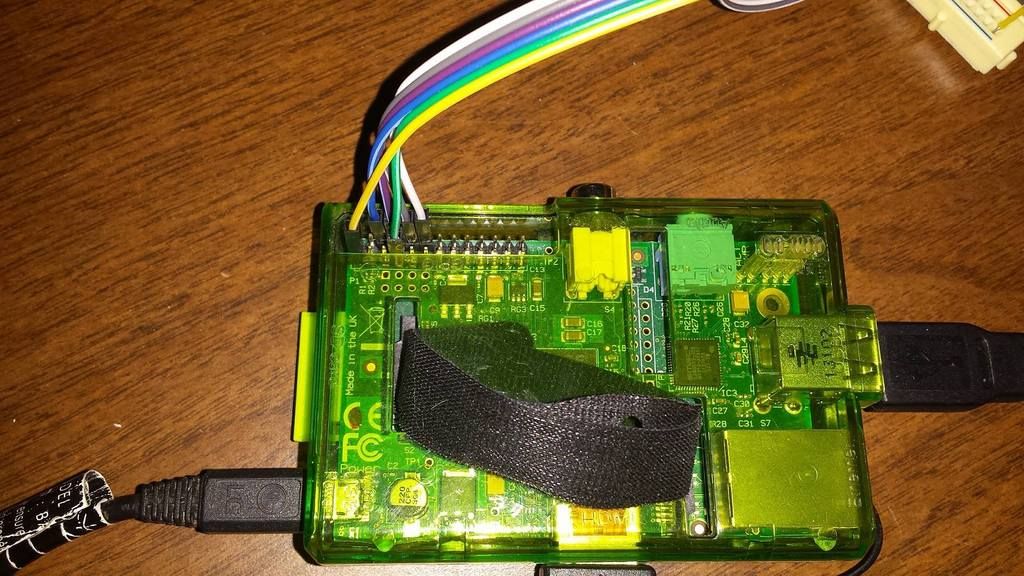
Funny business with the LED's after RetroPie starts tells me you probably have one of the wires flipped around. Unfortunately with that block in the way I can't get a good picture of which pins are going to which GPIO's. Please take that out, setup the driver with map=7,0,0,0,0,0 , and plug the data pin, with pull up resistor, to GPIO0, and post a picture. Then we'll go from there.
-
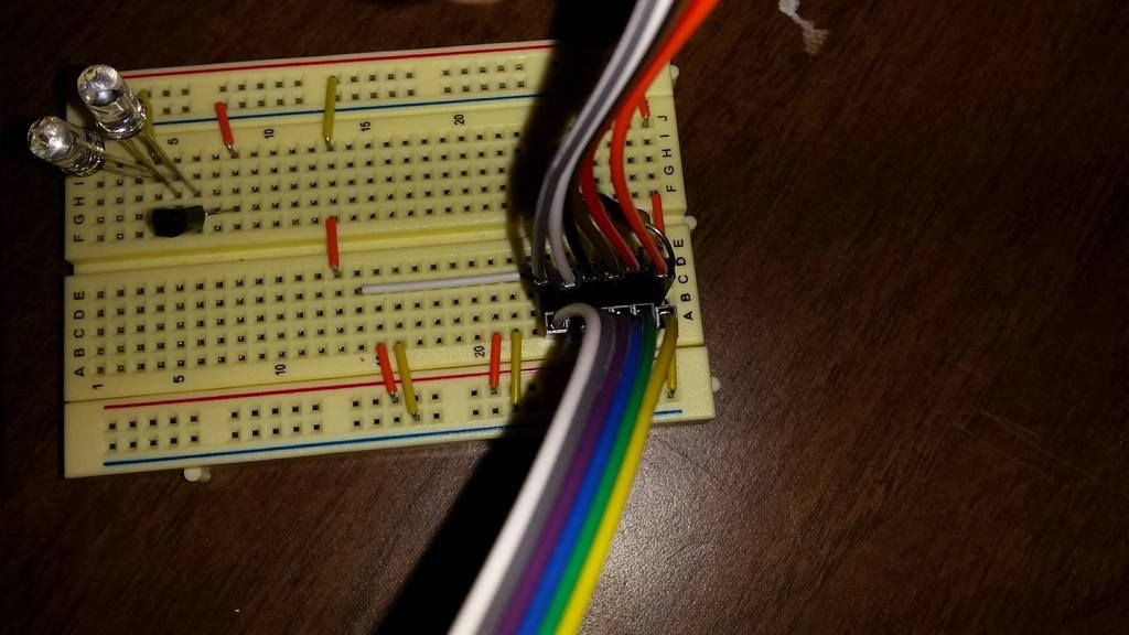
@Katemonster This is what I have currently.
 with options
 gamecon_gpio_rpi map=0,0,7,0,0,0in/etc/modprobe.d/gamecon.confBut I can take pictures hopefully later when I get home or tomorrow.
-
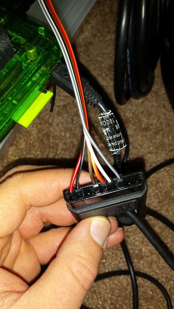
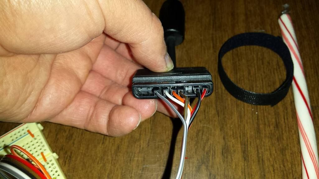
@Katemonster Took some pictures
-
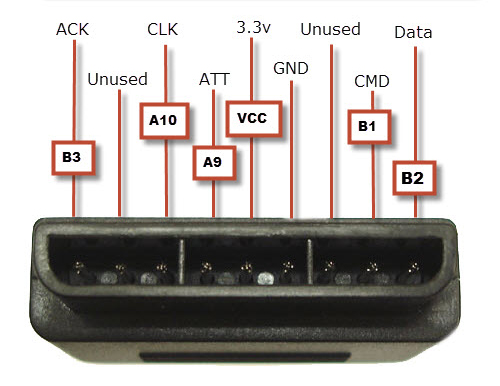
@geneworld OK, looks like your wiring is backwards. Use this diagram: psx pinout
-
@Katemonster well that could be an issue right?
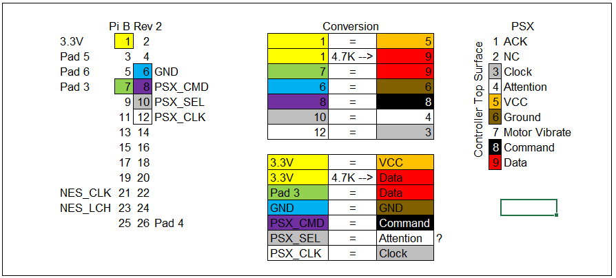
I've been using this one:
I'll switch to this one:

and see what I get! Great find this is promising I can't wait to swap it out after work!
-
@geneworld oh wow, yeah that diagram is completely backwards.
This explains why your controller was powered during boot, but not once retropie starts- the 3.3V pin is dead center, so that was correct, but ground was technically plugged in to the PSX_SEL line, which might tend towards ground with the module not loaded.
-
@Katemonster I'm excited to test this out, it will really advance my project!
So to stick with updated I will change my wire diagram to reflect this:
Contributions to the project are always appreciated, so if you would like to support us with a donation you can do so here.
Hosting provided by Mythic-Beasts. See the Hosting Information page for more information.