What am i doing wrong with my hd44780 16x2 lcd?
-
No I won't give up, I used the sd card from the rpi2 (where the lcd was working) and stuck it in the rpi3 with no dac attached and bingo!!
So now I'm going to reconnect the dac and try that. If that works also I know it's not a hardware issue :)
I'll start with a fresh image then add the ATXraspi and test lcd, add the DAC then test lcd.....and so on until either I find out the problem or it just works (and I never find out what the problem was)
Level shifter getting delivered this week hopefully. -
@Boz
I used the python libary posted here - it worked flawless with my setup. Keep care of upper and lower cases. Just use the same filenames as posted in the thread.Good luck mate
EDIT:
Just for conserving (INTERNET IS FLUID!)
Testing python snipletretropie.pyimport I2C_LCD_driver from time import * mylcd = I2C_LCD_driver.lcd() mylcd.lcd_display_string("Hello RetroPie!", 1) mylcd.lcd_display_string("Column 3!", 2, 3)LCD driverlibary
I2C_LCD_driver.py- change adress in driver for ex 0x27h
Please check withi2cdetect -y 1(ori2cdetect -y 0on Raspberry v1 B)# -*- coding: utf-8 -*- # Original code found at: # https://gist.github.com/DenisFromHR/cc863375a6e19dce359d """ Compiled, mashed and generally mutilated 2014-2015 by Denis Pleic Made available under GNU GENERAL PUBLIC LICENSE # Modified Python I2C library for Raspberry Pi # as found on http://www.recantha.co.uk/blog/?p=4849 # Joined existing 'i2c_lib.py' and 'lcddriver.py' into a single library # added bits and pieces from various sources # By DenisFromHR (Denis Pleic) # 2015-02-10, ver 0.1 """ # i2c bus (0 -- original Pi, 1 -- Rev 2 Pi) I2CBUS = 1 # LCD Address ADDRESS = 0x27 import smbus from time import sleep class i2c_device: def __init__(self, addr, port=I2CBUS): self.addr = addr self.bus = smbus.SMBus(port) # Write a single command def write_cmd(self, cmd): self.bus.write_byte(self.addr, cmd) sleep(0.0001) # Write a command and argument def write_cmd_arg(self, cmd, data): self.bus.write_byte_data(self.addr, cmd, data) sleep(0.0001) # Write a block of data def write_block_data(self, cmd, data): self.bus.write_block_data(self.addr, cmd, data) sleep(0.0001) # Read a single byte def read(self): return self.bus.read_byte(self.addr) # Read def read_data(self, cmd): return self.bus.read_byte_data(self.addr, cmd) # Read a block of data def read_block_data(self, cmd): return self.bus.read_block_data(self.addr, cmd) # commands LCD_CLEARDISPLAY = 0x01 LCD_RETURNHOME = 0x02 LCD_ENTRYMODESET = 0x04 LCD_DISPLAYCONTROL = 0x08 LCD_CURSORSHIFT = 0x10 LCD_FUNCTIONSET = 0x20 LCD_SETCGRAMADDR = 0x40 LCD_SETDDRAMADDR = 0x80 # flags for display entry mode LCD_ENTRYRIGHT = 0x00 LCD_ENTRYLEFT = 0x02 LCD_ENTRYSHIFTINCREMENT = 0x01 LCD_ENTRYSHIFTDECREMENT = 0x00 # flags for display on/off control LCD_DISPLAYON = 0x04 LCD_DISPLAYOFF = 0x00 LCD_CURSORON = 0x02 LCD_CURSOROFF = 0x00 LCD_BLINKON = 0x01 LCD_BLINKOFF = 0x00 # flags for display/cursor shift LCD_DISPLAYMOVE = 0x08 LCD_CURSORMOVE = 0x00 LCD_MOVERIGHT = 0x04 LCD_MOVELEFT = 0x00 # flags for function set LCD_8BITMODE = 0x10 LCD_4BITMODE = 0x00 LCD_2LINE = 0x08 LCD_1LINE = 0x00 LCD_5x10DOTS = 0x04 LCD_5x8DOTS = 0x00 # flags for backlight control LCD_BACKLIGHT = 0x08 LCD_NOBACKLIGHT = 0x00 En = 0b00000100 # Enable bit Rw = 0b00000010 # Read/Write bit Rs = 0b00000001 # Register select bit class lcd: #initializes objects and lcd def __init__(self): self.lcd_device = i2c_device(ADDRESS) self.lcd_write(0x03) self.lcd_write(0x03) self.lcd_write(0x03) self.lcd_write(0x02) self.lcd_write(LCD_FUNCTIONSET | LCD_2LINE | LCD_5x8DOTS | LCD_4BITMODE) self.lcd_write(LCD_DISPLAYCONTROL | LCD_DISPLAYON) self.lcd_write(LCD_CLEARDISPLAY) self.lcd_write(LCD_ENTRYMODESET | LCD_ENTRYLEFT) sleep(0.2) # clocks EN to latch command def lcd_strobe(self, data): self.lcd_device.write_cmd(data | En | LCD_BACKLIGHT) sleep(.0005) self.lcd_device.write_cmd(((data & ~En) | LCD_BACKLIGHT)) sleep(.0001) def lcd_write_four_bits(self, data): self.lcd_device.write_cmd(data | LCD_BACKLIGHT) self.lcd_strobe(data) # write a command to lcd def lcd_write(self, cmd, mode=0): self.lcd_write_four_bits(mode | (cmd & 0xF0)) self.lcd_write_four_bits(mode | ((cmd << 4) & 0xF0)) # write a character to lcd (or character rom) 0x09: backlight | RS=DR< # works! def lcd_write_char(self, charvalue, mode=1): self.lcd_write_four_bits(mode | (charvalue & 0xF0)) self.lcd_write_four_bits(mode | ((charvalue << 4) & 0xF0)) # put string function with optional char positioning def lcd_display_string(self, string, line=1, pos=0): if line == 1: pos_new = pos elif line == 2: pos_new = 0x40 + pos elif line == 3: pos_new = 0x14 + pos elif line == 4: pos_new = 0x54 + pos self.lcd_write(0x80 + pos_new) for char in string: self.lcd_write(ord(char), Rs) # clear lcd and set to home def lcd_clear(self): self.lcd_write(LCD_CLEARDISPLAY) self.lcd_write(LCD_RETURNHOME) # define backlight on/off (lcd.backlight(1); off= lcd.backlight(0) def backlight(self, state): # for state, 1 = on, 0 = off if state == 1: self.lcd_device.write_cmd(LCD_BACKLIGHT) elif state == 0: self.lcd_device.write_cmd(LCD_NOBACKLIGHT) # add custom characters (0 - 7) def lcd_load_custom_chars(self, fontdata): self.lcd_write(0x40); for char in fontdata: for line in char: self.lcd_write_char(line) -
Thanks m8,
i'll try that script when my level shifter comes, my displays a little dull at the minute on 3.3v.
Now I know the display can work, I'll implement it into the facia design. The lcd wasn't essential but damn it looks good!! -
@Boz Post pictures if you're ready with your build :)
-
@cyperghost will do m8, the level shifter came today so I'm gonna wire it up tomorrow if I get time. I'll post pics of the display working but it might be a while for the finished product.
I need a day when my boss isn't in so I can mill the facia.
Thanks for your time aswell m8, it's been much appreciated. You and future.child. -
Hi, I'm about to wire up this level shifter but I'm a bit confused on the wiring.
Is this right so far?Level Shifter/ Pi / LCD
LV / pin 1 (LV from level shifter to pin 1 on pi)
LV1 / pin 3 (LV1 from level shifter to pin 3 on pi)
LV2 / pin 5 (LV2 from level shifter to pin 5 on pi)
GND / pin 6 / GND (gnd from level shifter to pin6 on pi, opposite gnd on level
shifter to gnd on LCD?)
HV / pin 2 / VCC (HV from level shifter to pin 2 on pi, then?)
HV1 / SDA (HV1 from level shifter to SDA on i2c?)
HV2 / SCL (HV2 from level shifter to SCL on i2c?) -
@Boz You are 100% on the right track :)
L means Low
H means HighL1 = 3,3V and is connected to your Pi power Pin 1
H1 = 5,0V and is connected to your Pi power Pin 2
G = Ground connected to your Pi (3,3V and 5,0V and of course also LCD via Levelshifter)LV1 = SDA Pin 3 from your Pi
LV2 = SDL Pin 5 from your PiHV1 = SDA to your I2C LCD
HV2 = SDL to your I2C LCDGND is GND and doesn't matter were you connect to your Pi because voltage potential is equal!
You connect Ground from LCD to your Pi, also the 3,3V and 5,0V are connected to your Pi. You can seepicture in my postingUsually you can connect all grounds together.
But at first try I would use 3,3V/Ground and 5,0V/Ground seperate because they are needed to reference voltage level. -
So I connect the levelshifter GND LV side (3.3v) to pin 6 (GND) on the pi and GND HV side (5v) to say pin 9 (GND) on the pi also? How do I also connect GND from the levelshifter to the lcd with no GND pins left?
(Please bear with me I don't have a brilliant understanding of voltage etc)
ps: I'm using direct wiring and no breadboard. -
@Boz The best way is to connect every ground as single line - you will avoid interferences with that. But you can connect ground 3,3V to Pi ground and connect HV ground to I2C backpack.
But on the other hand (I didn't know you don't have a breakboard):
As they use all the some potential it isn't needed to wire every ground to annother point.
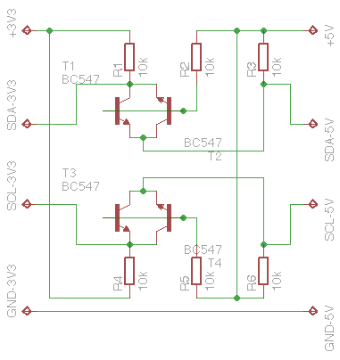
Here you see the shematics
I used one of my old B+ and used a Pi Dish but not for 25$ :))
-
I must have messed up somewhere there's no power to the lcd.
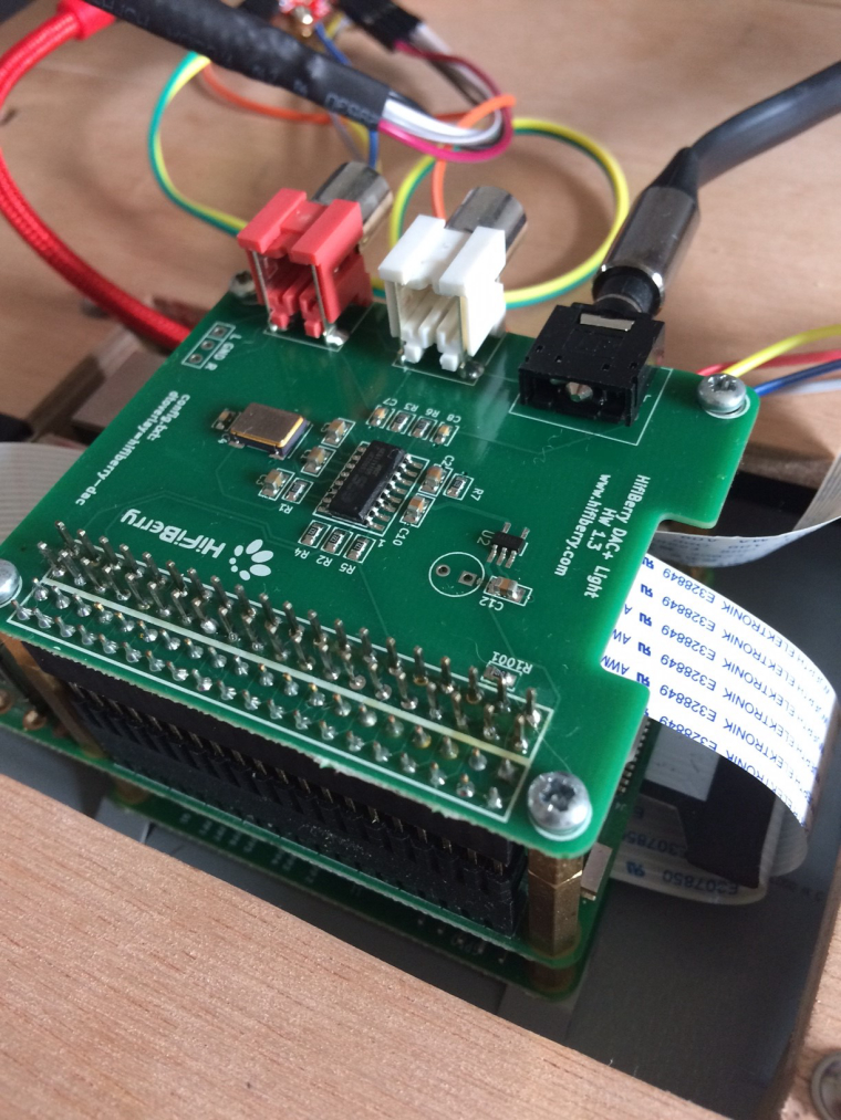
I have the wires connected as you said (will double check again in a min) but connected via the header on my dac.
I notice I didn't connect any wire to the vcc on the i2c backpack is this correct? -
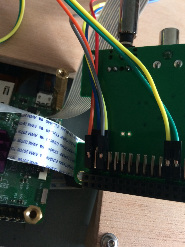
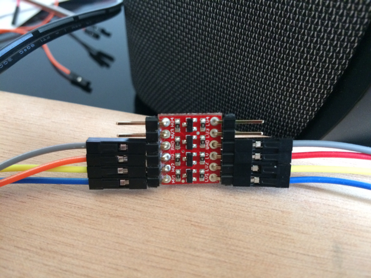
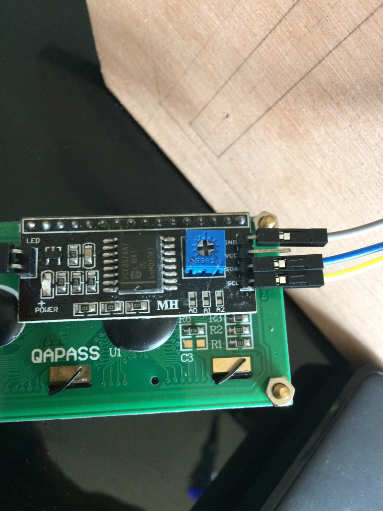
Here's some pics:
-
I have it wired like so:
LV (red) to pin1 on dac
HV (orange) to pin2 on dac
GND (grey) to pin6 on dac
GND (grey) to GND on i2c
LV1 (blue) to pin3 on dac
LV2 (yellow) to pin 5 on dac
HV1 (blue) to SDA on i2c
HV2 (yellow) to SDL on i2cNothing connected to VCC on i2c.
-
Can you measure voltage on HV? That has to be 5,0V
Then connect HV also to VCC on your I2C LCD - with 5,0VThe connection HV and LV on level shifter is only for internal comparism 3,3V and 5V it is not intended as supply. The LCD must glow if the there is 5,0V...
The Pi got annothe 5V pin... Pin2! Use that for LCD connect!EDIT: Sorry Pin 2 is already used... Can you expand it? Or what about Pin 4? You need 5V for the LCD!
-
Ok so I just add a wire from pin 4 on pi(dac) to vcc on i2c and leave the rest?
I thought the idea was to not directly connect 5v power to the i2c backpack ?
-
Yes
But I'm not sure if the device can be detected. I2C is multibus so it should work.... but we will see. Maybe I2C adresses from your devices are the same. Just connect and report!
Your have a seconds Pi.... maybe you can get it on this to work? -
Will connecting pin4 directly to the lcd not damage the pi?
I thought that was the reason I got the level shifter?If I was to solder a 2nd wire to HV header on the level shifter and connect that wire to VCC on the i2c would that solve the problem?
-
No...
There are voltage output pins!
2x 5V and 2x 3,3V ... The 5V can output the same amount as the power supply so very robust
the 3,3V can only output 40 or 60mA that's enough vor LEDs or a few IC.The rest are "sender" and/or "receiver" Pins.
They sending with 3,3V and if they are receiving data the voltage level should also 3,3V
5,0V is much to high... So the level shifter reduces or highers only the "sender" and "receiver" parts. It has nothing to do with the power supply. Got it?You can also try to split the Pin1 to work with level shifter and LCD.
-
Thanks now I understand,
I'll solder a wire onto the HV pin then and see what happens :)LV (red) to pin1 on dac
HV (orange) to pin2 on dac / VCC on i2c
GND (grey) to pin6 on dac
GND (grey) to GND on i2c
LV1 (blue) to pin3 on dac
LV2 (yellow) to pin 5 on dac
HV1 (blue) to SDA on i2c
HV2 (yellow) to SDL on i2c -
Yes ... Seems right now
-
Contributions to the project are always appreciated, so if you would like to support us with a donation you can do so here.
Hosting provided by Mythic-Beasts. See the Hosting Information page for more information.