Super Nintendo / Famicom Controller ports to Pi Zero GPIO (No ControlBlock)
-
Hi everyone
I am having a bit of trouble, i have read numerous threads and guides about connecting the original controller ports directly to the GPIO pins on a raspberry pi without using Peter Blocks ControlBlock. But i am getting a lot of conflicting information as to which GPIO pins to connect to.
If anyone can help i need a clear working guide for both controllers to connect to the pins on a Raspberry Pi Zero. Any info or guides will be much appreciated.
Many thanks
-
I have seen several similar projects on these forums, can anybody point me to a working guide to wire up the original snes controllers to the Pi Zero GPIO pins using the controller port on the front of the console.?
Many Thanks
-
@ceeeeee4 You can use the gamecon driver schematic from its installer in retropie setup. I think the schematic pops up when you configure the default which are two snes controllers. I'm not sure if the pinout's changed from a pi zero to a pi2/3 but if it hasn't, it should work. More info here https://github.com/RetroPie/RetroPie-Setup/wiki/GPIO-Modules#gamecon_gpio_rpi
-
All 40 pin Raspberry Pi's (2/3/0/0w) use the same GPIO layout. The only difference is that you don't have the pins populated on the zero. So if you follow a pi2/3 wiring, this should work.
-
Thanks for the replies guys. i have the gamecon driver installed and can see the schematic of which GPIO pins to connect to, but which pins on the snes controller board do i use?
i would like both controllers working and the power LED if possible. would really appreciate the help.
many thanks
-
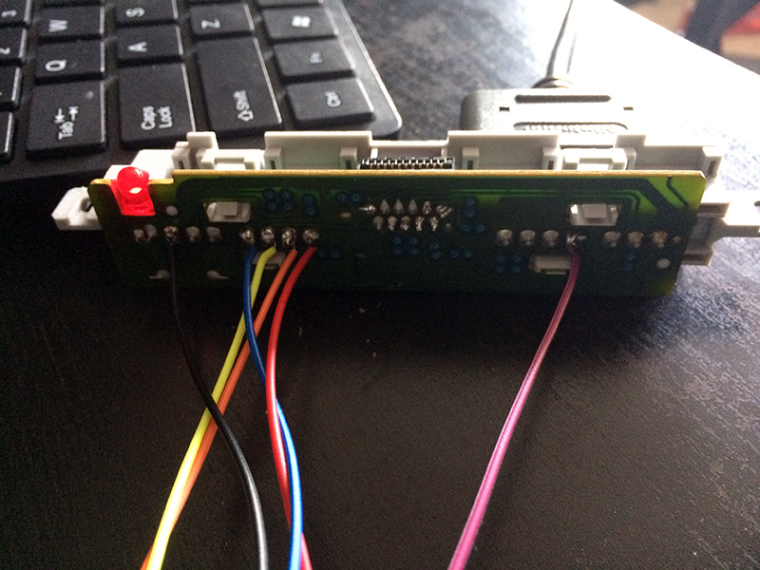
i have wired it up using the gamecon driver schematics. i have used these pins from the snes controller board (see pic). the LED lights up on power on, but i can only input the B button..
Any ideas??

-
@ceeeeee4 Do what I recommended you to do and use the schematic that pops up from the gamecon driver setup in retropie-setup.
I found my old post. These are the pins I used. Led works. It's for two snes pads:
Pin1=3.3v
Pin5=D2
Pin6=GND
Pin7=D1
Pin19=C1/C2
Pin23=L -
thank you sir that has worked. i didint have both clock pins going to the pin 19.
Contributions to the project are always appreciated, so if you would like to support us with a donation you can do so here.
Hosting provided by Mythic-Beasts. See the Hosting Information page for more information.