Pi in a Gameboy Advance Build - WIP
-
I finally got around to shopping for some ferrite beads today, and wow, shop around online. The ones I was looking for were part number 86-1570 as referenced on sudomod. I found a shop in Connecticut that had them for $2/pack instead of the $9/pack they were selling for on eBay. If I lived anywhere near a Fry's, that would have been an option too, but sadly, I do not. They should be here in a few days to a week. I also see that Camble's safe shutdown circuit will fit in my case as it's 30mmx15mm. Hopefully they will be available for purchase soon as that will solve my "how do I shut this thing off nicely?" problem.
I'm not sure how I want to go about getting the LED to work. Ideally I'd love it to display in the original spot and be green when on and orange when charging, but I'm not sure if there's a good way to go about doing that.
-
I love when parts come in the mail!
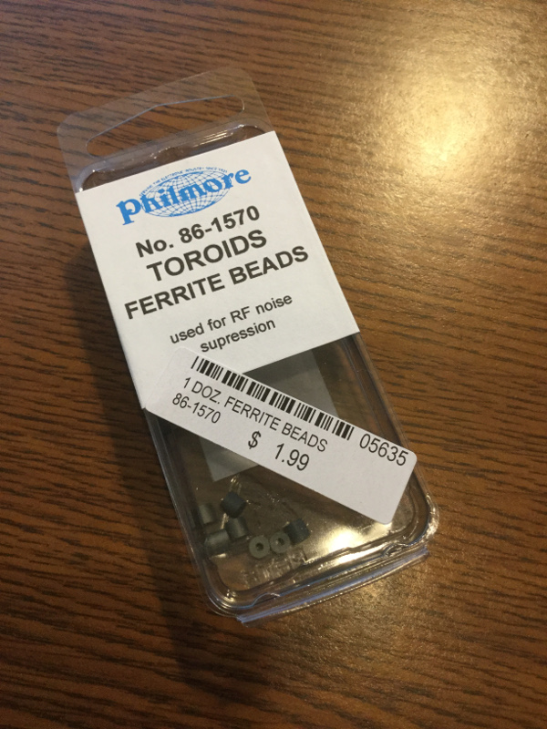
My ferrite beads arrived, and wow, they're really tiny. I didn't get out my micrometer, but a quick measurement with a ruler has them at just a shade over 3mm in diameter.
I also got a USB current tester. I wanted to see how much this rig was pulling with the screen, USB sound card, amplifier, and wifi enabled, and with SFA 3 playing on lr-mame2003 and the amp turned ALL the way up, it was peaking at 520mA at 5V. I don't think I'll be having issues with the PowerBoost 1000c not being able to keep up.
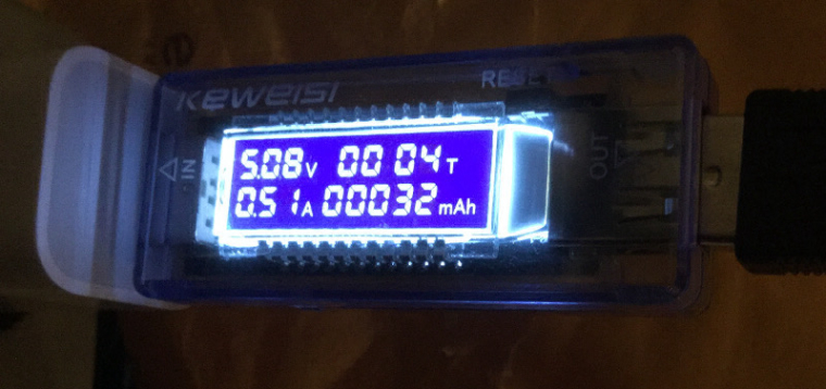
I did find that when I switched over to lr-genesis-plus-gx, again, with the volume totally maxed out, that I would get the lightning bolt, the red light would blink, and things would sputter. I turned down the volume at the knob (not on the amp itself) and things cleared up. That told me that the amp was the issue. Even though my current tester said the whole system wasn't drawing more than 460mA at the time, I know that the USB ports are limited in power output, and since I have to power the amp from USB to avoid the buzzing from the power supply/SOC, I decided to see if increasing the maximum output to the USB ports would help.
I set
max_usb_current=1in/boot/config.txtand rebooted. Same problem. I then turned down the volume on the amplifier from "all the way up" (It doesn't go to 11), down to about half way, and everything works fine, no lightning bolt, even wit the volume knob turned all the way up and the ALSA mixer turned up to 80.With the amp setting dialed in I decided to see how much power everything would use over time. Letting Ghouls 'n Ghosts run its demo loop in lr-genesis-plus-gx for 30 minutes, with the volume all the way up, I saw on the current tester that it used 244mA at 5V. I'm not sure how to convert that to 3.7V, or to factor in the efficiency of the PowerBoost, but with a 2500mAh battery, I should get a few hours of play time out of this. At least I think so.
-
@obsidianspider looking good! I take it the beads have totally cured the sound issues?
The power calculations can be done simply. If we use basic wattage calculation. You half hour test used 250ma (rounded of course) so we can assume 500ma for the hour. If we multiply that by the voltage (in guessing 5.1, can't see the image right now) then that gives us a total of 2.55 watts.
We can then divide that by the battery voltage to reverse calculate it. The battery voltage will range from 4.2-3.2ish so if we use 3.7v as an average, we can take the 2.55 watts, divide that by the 3.7 and that gives us the magical number of 689mah so we can round that up to 700mah.
This may be slightly more in real world usage. Most boost converters loose some power in operation, but you should be over 3 hours with a 2500mah battery
-
@obsidianspider
A "USB current tester" ... I didn't know such a thing like this existed...but I need one now!! -
@backstander they are petty handy. Nice and cheap, although I think mine reads about 10% low
-
@backstander said in Pi in a Gameboy Advance Build - WIP:
@obsidianspider
A "USB current tester" ... I didn't know such a thing like this existed...but I need one now!!I'm also going to get a female JST connector and connect it to a female USB plug so I can test current draw directly from a LiPo.
-
Well…
It looks like I broke something.
Today I decided to desolder the speaker leads, put the ferrite beads on, and test things out to see if the "hiss" was reduced. I can't really tell how much it was reduced, but unless I put my ear right next to the speaker, I can't hear it, so that's good.
So, what did I break? Well, I think I fried something, either in the Pi, or the iBuffalo controller, or both. I'd been using an iBuffalo controller hooked up via USB to do testing and when I powered things up to test the speaker, it wasn't detected.
lsusbdidn't show it, nothing.Since I was maxing things out and was getting the blinking power LED on the Pi I figured I fried something in the USB circuit, but it couldn't be everything, as the USB sound card still showed up. I removed the hot glue at the Pi and retouched the solder points, then I tested continuity from the plug back to the Pi, all good. Then since things still weren't working, I made sure I was getting 5V at the plug, I was. Then I took an old USB drive and plugged it in. It worked.
Then I got an old Gravis Gamepad Pro and plugged it in. It worked. Weird. Then, just for the heck of it, I plugged a USB hub (not powered) into the USB port, and then plugged the iBuffalo into that. The iBuffalo worked. I don't know why, but it will work through a hub, but not directly plugged into the Pi.
I then tested the iBuffalo directly plugged into my test Pi Zero, and it works there, and it also works plugged into my laptop. I'm not sure what's up, but I'm mad at myself for breaking whatever went wrong. I guess when you push the envelope, you're going to break parts.
I'm not sure what I'll ultimately end up doing with this build regarding having an exposed USB port, but at least for now I still have ways to test before I get the buttons in the shell.
-
I don't know why, but it will work through a hub, but not directly plugged into the Pi.
That is odd, I wonder if the solder joints are too close together?
-
@backstander yet other devices work when directly plugged in. So weird. I'm not going to let it derail the project. I'm more mad at myself for frying something.
-
@obsidianspider Could the ferrite beads be causing anything? It is very odd!
-
@moosepr Nope, because the controller not working happened before the ferrite beads were introduced into the picture. My initial intent was to just try hooking up the tiny piezo speaker by touching the leads to the amp, but when the controller didn't work, plans changed.
To try to figure out what the heck was going on, I Googled around, as one does, and saw that one suggestion for a device not working on one computer, but working on others was that maybe drivers were messed up. I took my spare SD card, put a fresh image of retropie on it, popped it in my Pi 2, and the iBuffalo worked directly plugged into the Pi 2. I added the necessary framebuffer stuff to get the display to output to the TFT, then took the card out and put it in the GBA Pi 3, with the iBuffalo plugged in. No controllers detected message from EmulationStation. I plugged in my Gravis Gamepad Pro, it worked. I plugged in a USB drive, it worked. I plugged in a keyboard, it worked. Even though this Pi obviously has something up with it, I plugged in my "good" Raphnet-converted SFC controller, it worked. It's just that one controller on that one Pi. So bizarre.
The next thing I really need to do is to get some small glass jars so I can make some ABS cement and finally tackle the case mod. The power circuit is on hold until Camble has more safe shutdown boards for sale, or I figure something else out, and I can't fit audio components all in the case until I get it modded for ABXY.
I could buy another Pi 3, cut it down, hope I don't mess it up, and go again, but considering I don't even know if this USB port will be hooked up/exposed, I don't know that I want to go through that effort, especially since other USB devices do work.
-
@obsidianspider that is really weird! The controller works in another pi, and the USB works for other devices! In assuming you are just using the controller for testing? Will it be used in the final build?
-
@moosepr Yeah, it is weird. Now I'm wondering what broke. I'm almost positive that it was during the stress testing, but what weird was that the controller worked fine during the test, and even yesterday after a few reboots. I was using it for testing as I like the SNES controller form factor, and since it's a dodgy cut up Pi, if I did break something I didn't want to break my "good" Raphnet controller. The Pi also recognizes the iBuffalo controller if I plug it into a hub, and plug the hub into the Pi. So. Weird.
The final build will be using the GBA and DS Lite PCBs connected directly to GPIO for controls via Retrogame.
-
You won't be using that USB port at the end right? This is just for testing right?
You gonna connect the controls to the GPIO?If the answer to all 3 is yes then forget about it and continue...
Important is the final result.
iBuffalos are weird controllers anyway, like having a mind of their own. ;-) -
Testing ABS cement on the battery door went really well. I applied four small blobs of glue on the inside of the door and it set up clear. There are some small air bubbles in it, which I knew to expect, but since it's inside the case, I'm just going to let it. I think it's strong enough that I won't bother to add more glue. If anything, I may fill the hole where the battery door clip was (I had to cut it off as it stuck out inside the case), but aside from that, I'm calling this a success. From the outside, there's no warping or signs that it was glued at all.
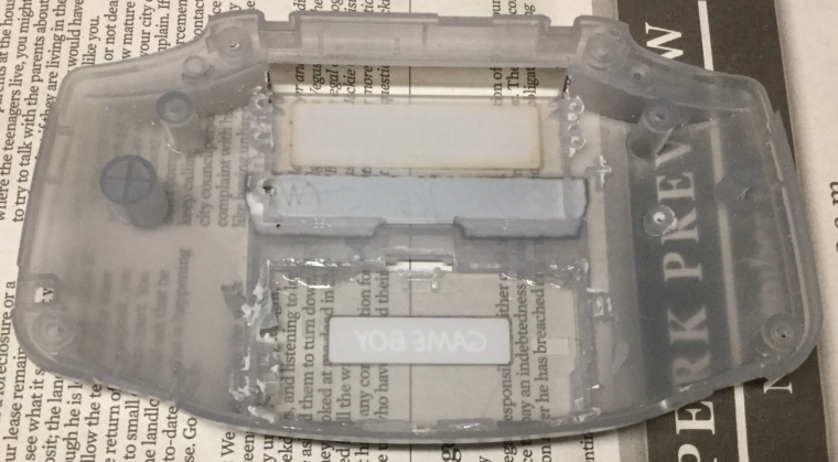
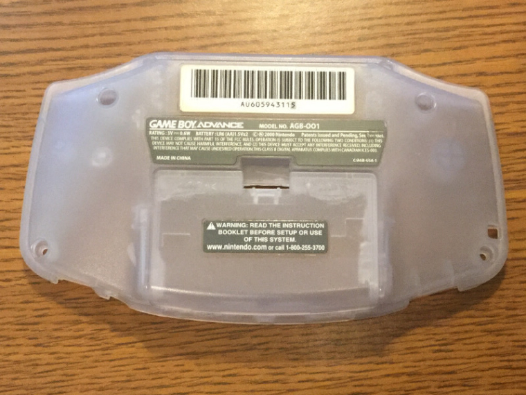
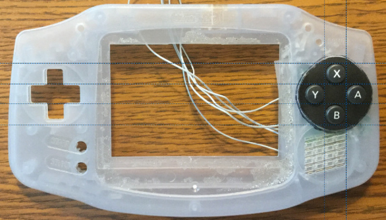
Given that success, I decided to take the leap and try to combine the DS Lite ABXY button area with the front of the GBA. I cut out the area from the DS Lite and after a lot of measuring, I marked the case on the GBA.
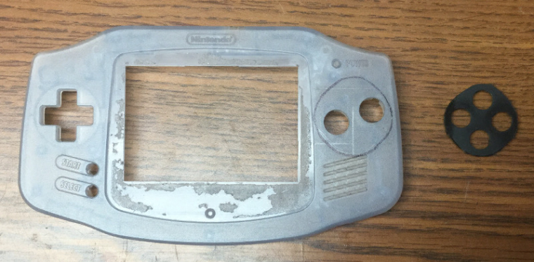
I then used a Dremel, file, and xacto knife to trim the hole. I accidentally bumped the case with the Dremel chuck, which bugs the heck out of me, but since I will be using some filler to smooth things over for the buttons,it should be be OK, but geeze. I also nicked my finger when I was using the xacto knife and it slipped. Be careful kids.
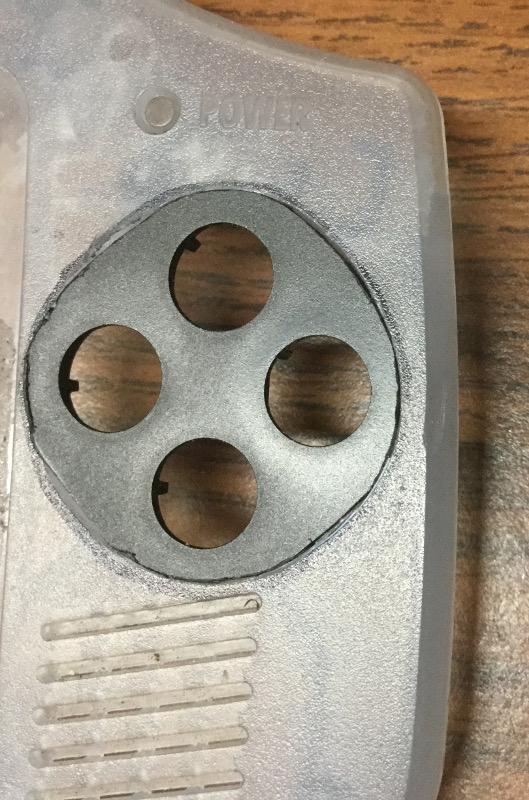
Now I'm at a point where I need to decide if things are lined up properly before attempting to join them permanently. I've tacked the DS Lite plastic in with some hot glue, but I need a few more sets of eyes on this. With a lot of measuring I think I'm within fractions of a millimeter of perfectly straight, but I'd rather get some feed back before I can't easily undo things.
What do you think?
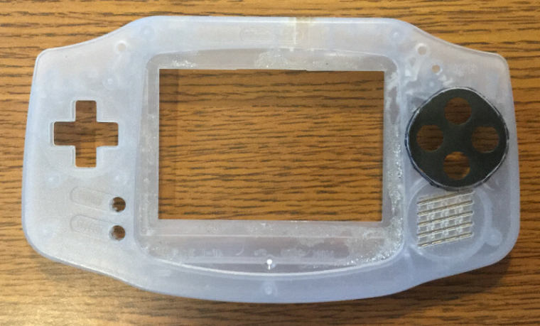
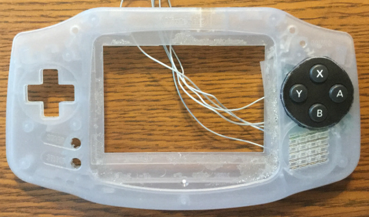
-
@obsidianspider you can't deny those lines! Looks good to me!
-
@obsidianspider said in Pi in a Gameboy Advance Build - WIP:
OK, I'm back in business. That "octopus" hub is just a piece of junk. I updated the wiki entry to reflect my findings.
I went to Best Buy on my lunch break and picked up the Targus ACH114US that was listed as the "original" Gameboy Zero hub and it works perfectly. With my wifi adapter, usb controller, usb keyboard and usb soundcard everything is operating as it should.
lsusb -t
/:  Bus 01.Port 1: Dev 1, Class=root_hub, Driver=dwc_otg/1p, 480M
    |__ Port 1: Dev 2, If 0, Class=Hub, Driver=hub/4p, 480M
        |__ Port 1: Dev 3, If 0, Class=Human Interface Device, Driver=usbhid, 1.5M
        |__ Port 2: Dev 6, If 0, Class=Audio, Driver=snd-usb-audio, 12M
        |__ Port 2: Dev 6, If 1, Class=Audio, Driver=snd-usb-audio, 12M
        |__ Port 2: Dev 6, If 2, Class=Audio, Driver=snd-usb-audio, 12M
        |__ Port 2: Dev 6, If 3, Class=Human Interface Device, Driver=usbhid, 12M
        |__ Port 3: Dev 5, If 0, Class=Human Interface Device, Driver=usbhid, 1.5M
        |__ Port 3: Dev 5, If 1, Class=Human Interface Device, Driver=usbhid, 1.5M
        |__ Port 4: Dev 4, If 0, Class=Vendor Specific Class, Driver=rtl8192cu, 480M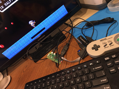
While it works, it's pretty long. Which is the main reason I went with the "octopus" hub originally.
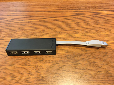
Taking it apart was pretty easy, but I'm going to have to think about how I am going to be able to fit it inside the Gameboy Advance shell.
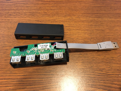
Another neat thing I learned. The Targus hub has five wires, but it's only USB 2. The plug only has four pins. The fifth blue wire is apparently a "drain" wire and is tied to ground and is connected to all of the metal on the plug and on the socket surrounds.
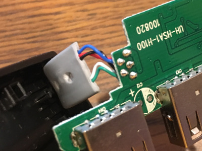
I've been using this same Targus 4 port usb hub for my retropie builds. They work great! I'm curious to learn more about the blue "drain" wire. How'd you find out about that? Does it work without the blue wire? I kind of snapped the blue wire on one of mine...
-
@klachow I believe the drain wire is so if there is a static discharge it will ground through that wire. It's connected up to the metal sheath on the USB port itself, not the pins. It should work fine if that's not connected.
-
@obsidianspider Interesting, that makes sense. Thanks!
-
@klachow enjoy watching your install! On the subject of USBs I don't know much but I googled around and found this site. It may be overkill but it has a lot of info. http://www.usbmadesimple.co.uk/index.html
Check it out.
Contributions to the project are always appreciated, so if you would like to support us with a donation you can do so here.
Hosting provided by Mythic-Beasts. See the Hosting Information page for more information.