RetroPie forum home
    • Recent
    • Tags
    • Popular
    • Home
    • Docs
    • Register
    • Login

    Pi in a Dreamcast VMU Build - WIP

    Scheduled Pinned Locked Moved Projects and Themes
    buildprojecthandheldvmudreamcast
    157 Posts 7 Posters 94.4k Views
    Loading More Posts
    • Oldest to Newest
    • Newest to Oldest
    • Most Votes
    Reply
    • Reply as topic
    Log in to reply
    This topic has been deleted. Only users with topic management privileges can see it.
    • obsidianspiderO
      obsidianspider
      last edited by

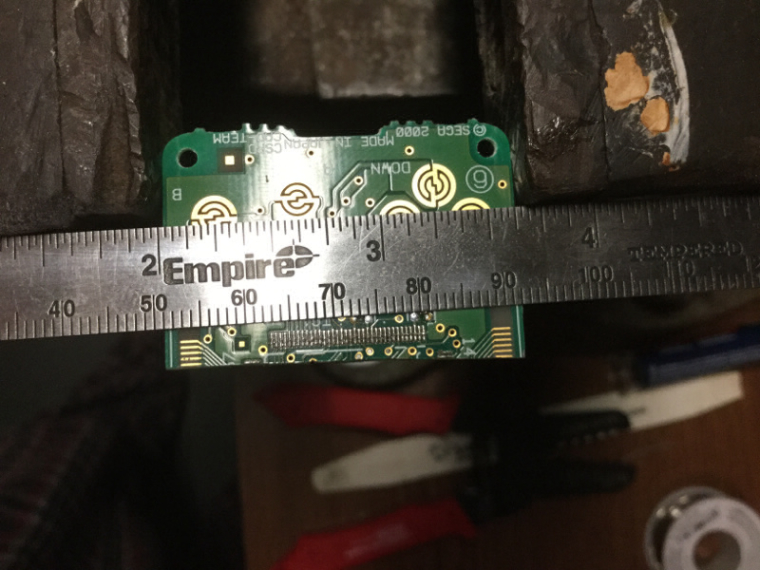
      Thanks to someone taking the forum offline this morning, I was working in the garage most of the day on this VMU stuff. I managed to find that only Up and Down have test pads, but I did find which pins on the chip correspond to which button.

      Button    Pin
      -------------
      Up        25
      Down      26
      Left      27
      Right     28
      A         29
      B         30
      Mode      31
      Sleep     32
      

      The problem I had was that I couldn't manage to attach wires to the really fine pads on the PCB.
      0_1491081857088_half-mm-pitch.jpg

      I decided to try to scratch my own test pads on the board, but that ended up not working well when I tried to attach a wire, and due to flux being on the board, and me not being as careful as I should have been, solder flowed over the carbon pad contact. I tried finishing, but the carbon pads just didn't work. Luckily I had another VMU to use.

      Having learned from the first attempt, I was more careful and managed to get leads connected up to the board.

      0_1491081965574_wired-up.jpg

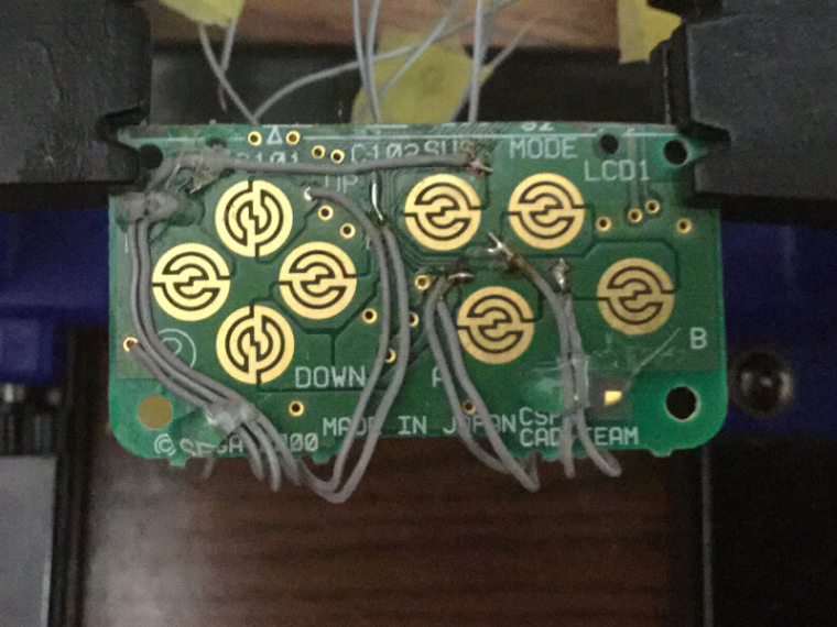
      Using Retrogame I found that things worked, but I found that Left and Up weren't registering quite right, and were hard to press. I rerouted the cables a bit and it was much better. I also see that the Sleep button doesn't stick out as far from the case as Mode so it's not as easy to press, but considering that you don't really press Select much during play, it's fine. I will likely tweak things more when I get more parts in, but I'm happy with how things are working, even if I did learn a $6 lesson in patience this morning.

      0_1491081978111_test-playing.jpg

      📷 @obsidianspider

      mooseprM 1 Reply Last reply Reply Quote 2
      • mooseprM
        moosepr @obsidianspider
        last edited by

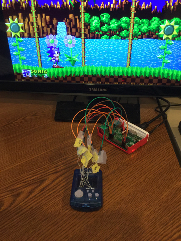
        @obsidianspider awesome job! Those pads will probably still work covered in solder. Will maybe oxidise faster though I guess

        want to get a tft into your project, look no further than here https://retropie.org.uk/forum/topic/7464/ili9341-tft-screen-guide

        1 Reply Last reply Reply Quote 1
        • mooseprM
          moosepr @ABrugsch
          last edited by

          @ABrugsch nerdfest! Ha ha I should sell them!

          want to get a tft into your project, look no further than here https://retropie.org.uk/forum/topic/7464/ili9341-tft-screen-guide

          1 Reply Last reply Reply Quote 0
          • obsidianspiderO
            obsidianspider
            last edited by

            @moosepr said in Pi in a Dreamcast VMU Build - WIP:

            dtoverlay=pwm,pin=18,func=2

            Your method worked! I'm not sure why my earlier attempt at using the overlay from Adafruit and only using one channel caused it to fail, but I only wanted mono anyway, so your solution was better. It's quiet, but loud enough I guess. Still not sure if thing will fit with the stock piezo and shell, but it opens the door to that small SMT one you mentioned. Maybe attach leads to it and glue it to the case?

            Here's a little test video.

            📷 @obsidianspider

            mooseprM 1 Reply Last reply Reply Quote 1
            • mooseprM
              moosepr @obsidianspider
              last edited by

              @obsidianspider wooohooo! It's amazing how much difference that casing makes

              want to get a tft into your project, look no further than here https://retropie.org.uk/forum/topic/7464/ili9341-tft-screen-guide

              obsidianspiderO 1 Reply Last reply Reply Quote 1
              • obsidianspiderO
                obsidianspider @moosepr
                last edited by

                @moosepr Given that these piezos like something to resonate, do those SMT ones need to be soldered to a board, or do you think I would be able to get a decent result from soldering up leads and then gluing it to the case itself? I don't see me creating a custom PCB for this. At least this iteration.

                📷 @obsidianspider

                mooseprM 1 Reply Last reply Reply Quote 0
                • mooseprM
                  moosepr @obsidianspider
                  last edited by

                  @obsidianspider they seem to work ok just soldered to wires. they are encased so they can work on there own. the one im testing is just on wires, and resting on the board

                  want to get a tft into your project, look no further than here https://retropie.org.uk/forum/topic/7464/ili9341-tft-screen-guide

                  1 Reply Last reply Reply Quote 0
                  • obsidianspiderO
                    obsidianspider
                    last edited by

                    I just got the mail, and wow, when @celly said he would include "some other goodies" in with the VMUs he was sending, he wasn't kidding. Thank you again @celly!

                    0_1491416842437_from-celly.jpg

                    📷 @obsidianspider

                    cellyC 1 Reply Last reply Reply Quote 1
                    • mooseprM
                      moosepr
                      last edited by

                      WOW!!

                      want to get a tft into your project, look no further than here https://retropie.org.uk/forum/topic/7464/ili9341-tft-screen-guide

                      1 Reply Last reply Reply Quote 1
                      • cellyC
                        celly @obsidianspider
                        last edited by celly

                        @obsidianspider yes! Glad you got it all. Can't wait to see the finished product.

                        Currently Playing: Tetris (Gameboy)

                        1 Reply Last reply Reply Quote 1
                        • A
                          ABrugsch
                          last edited by

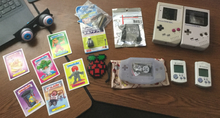
                          are those actual Garbage Pail Kids? wow memories!
                          (or do they still make them?) one of the things that annoyed me moving from USA to UK as a kid was that the garbage pail kids got smaller, and went from having a cutout shape for the sticker part to just being fully rectangular. I think I ended up throwing my collection away, or just sticking them to things...

                          obsidianspiderO 1 Reply Last reply Reply Quote 1
                          • obsidianspiderO
                            obsidianspider @ABrugsch
                            last edited by

                            @ABrugsch They're Garbage Pail Kids!

                            0_1491478569732_gpk.jpg

                            📷 @obsidianspider

                            1 Reply Last reply Reply Quote 1
                            • obsidianspiderO
                              obsidianspider
                              last edited by

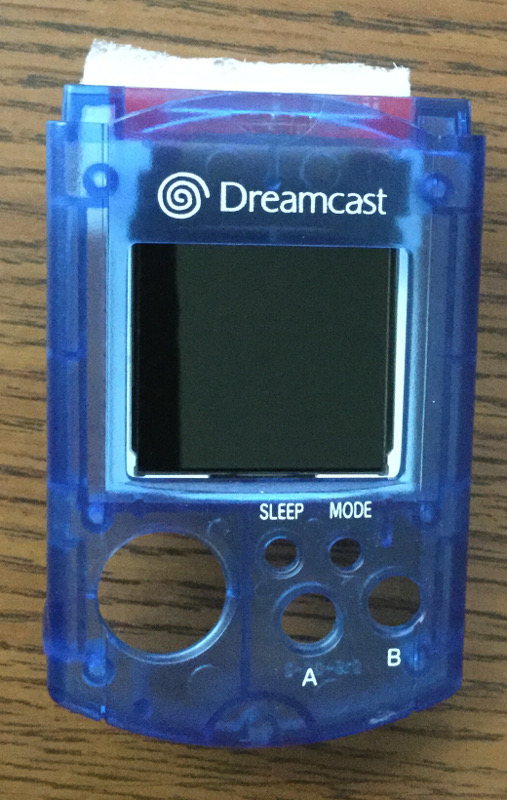
                              My screens showed up in the mail today!

                              No protective stickers over the actual display itself, so hopefully the minor imperfections I'm seeing on both screens are just some dirt.

                              0_1491850466296_vmu-screens-arrived.jpg

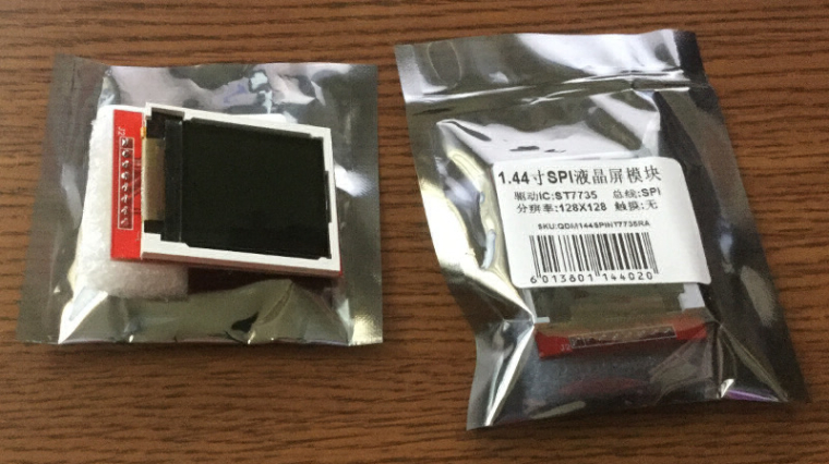
                              A quick mockup of setting a screen inside a VMU looks very promising.

                              0_1491850523748_screen-in-vmu-mockup.jpg

                              📷 @obsidianspider

                              mooseprM 1 Reply Last reply Reply Quote 1
                              • mooseprM
                                moosepr @obsidianspider
                                last edited by

                                @obsidianspider chip at the top sure it better!! plus the driver being upside down to begin with, means not having to worry about changing it!

                                want to get a tft into your project, look no further than here https://retropie.org.uk/forum/topic/7464/ili9341-tft-screen-guide

                                obsidianspiderO 1 Reply Last reply Reply Quote 0
                                • obsidianspiderO
                                  obsidianspider @moosepr
                                  last edited by

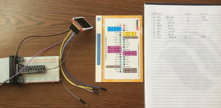
                                  @moosepr Now I'm trying to figure out what GPIO pins map to the pins on the red board.

                                  📷 @obsidianspider

                                  mooseprM 1 Reply Last reply Reply Quote 0
                                  • mooseprM
                                    moosepr @obsidianspider
                                    last edited by

                                    @obsidianspider is this any use?

                                    linez

                                    want to get a tft into your project, look no further than here https://retropie.org.uk/forum/topic/7464/ili9341-tft-screen-guide

                                    obsidianspiderO 1 Reply Last reply Reply Quote 1
                                    • obsidianspiderO
                                      obsidianspider @moosepr
                                      last edited by

                                      @moosepr This is about where I'm at. Your diagram helps quite a bit. I'll have to see if I can follow the traces and translate that to the pins on the red board before I try soldering things up. I want to make sure things work stock before I take it apart.

                                      0_1491854589717_figure-out-pins.jpg

                                      📷 @obsidianspider

                                      mooseprM 1 Reply Last reply Reply Quote 0
                                      • mooseprM
                                        moosepr @obsidianspider
                                        last edited by moosepr

                                        @obsidianspider lets see if i can fill in the blanks for you
                                        1 - 3.3v
                                        2 - gnd
                                        3 - gpio 8 (pin 24)
                                        4 - gpio 25 (pin 22)
                                        5 - gpio 24 (pin 18)
                                        6 - gpio 10 (pin 19)
                                        7 - gpio 11 (pin 23)
                                        8 - 3.3v (can be the same as pin 1)

                                        my schematic is a little messy, lots of crossovers. tis something i need to refine

                                        want to get a tft into your project, look no further than here https://retropie.org.uk/forum/topic/7464/ili9341-tft-screen-guide

                                        obsidianspiderO 2 Replies Last reply Reply Quote 0
                                        • obsidianspiderO
                                          obsidianspider @moosepr
                                          last edited by

                                          @moosepr Well, it looks like I came up with the same answer, so that's good. Now I need to tweak a RetroPie setup to see if I can get things working!

                                          📷 @obsidianspider

                                          mooseprM 1 Reply Last reply Reply Quote 0
                                          • mooseprM
                                            moosepr @obsidianspider
                                            last edited by

                                            @obsidianspider thats the easy bit

                                            raspi-config - enable spi

                                            sudo nano /etc/modules - add in

                                            spi-bcm2835
                                            fbtft_device

                                            sudo nano /etc/modprobe.d/fbtft.conf - add in

                                            options fbtft_device name=fb_ili9163 gpios=reset:25,dc:24 speed=40000000 bgr=1 rotate=0 custom=1 fps=60

                                            reboot

                                            want to get a tft into your project, look no further than here https://retropie.org.uk/forum/topic/7464/ili9341-tft-screen-guide

                                            obsidianspiderO 1 Reply Last reply Reply Quote 0
                                            • First post
                                              Last post

                                            Contributions to the project are always appreciated, so if you would like to support us with a donation you can do so here.

                                            Hosting provided by Mythic-Beasts. See the Hosting Information page for more information.