Advise Needed for Wiring Rocker Switch to Power Entire Retropie Arcade
-
Hello everyone. I've been researching this topic for days now and cannot find a good answer and am hoping the community here can advise some suggestions. So, I'm in the middle of my first retropie bartop arcade build and am stuck. I have the retropie, gamepad (buttons/joystick), and many other things working great, but, I'm stuck on the power thing. My objective is to have my retropie bartop arcade hang on the wall with french cleats (or whatever means that works), so, the backside of the cabinet will be open and I will install a new outlet on that wall to hide the power so there will be no visible wires. Now, here is the question .. I would like to have one single rocker button on the side of my arcade build to power OFF all things plugged into a power strip I have in the back (which will have the pi, led lights, audio amp, and monitor all plugged in). Is this even possible, and if so, how can/should this be wired? Ideally, I would like to cut my power strip and wire up that rocker switch. I've included a diagram of my idea .. but I'm unsure if this is even possible and if so, the exact correct wiring. The rocker switch I bought is an SPST Type 3 Pin ON/OFF Rocker Switch 10A/125V from Amazon: https://www.amazon.com/gp/product/B06XGSSPHP/ref=od_aui_detailpages00?ie=UTF8&psc=1
Again, ideally, the on/off rocker switch would be mounted on the side of the retropie arcade cabinet and would turn off all components for the arcade. Obviously, one would have to do the proper shutdown of the retropie first, then hit that OFF rocker switch to turn off everything else (monitor, led lights, audio amp). Thank you!!
-
@mb Most people use a fused switch socket for their bartop arcade. The fuse helps if you have a sudden power surge or such so you don't fry your components.
https://www.amazon.ca/Artrinck-Socket-Rocker-Switch-IEC320/dp/B0795S569L/ref=sr_1_5?ie=UTF8&qid=1523490021&sr=8-5&keywords=switch+socketAnd this is how it is wired :
Nevermind the comments under the video about the switch light not turning off. It does as this is how I wired mine and it works perfectly.
-
Make sure that switch is rated for the voltage you are running. 120 volts will blow right through an improper switch.
-
If your looking to have the plug and all hidden, you have a few options based on your electrical knowledge...
You can install a single pole switch and have the power strip go through that...
Or you can get a switched extension cord and stick the switch on the extension cord on the outside
-
I agree the fused switch that @ByteThis listed is a good idea in general, but if you are wiring a power strip it has a built in surge protection to it. Also that item will force a power cord on the out side of the cabinet which you are trying to avoid.
Also agreed it is important, getting a switch rated for your voltage. The one you list is fine for this use.
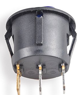
The copper on the left is ground (IE green) the middle will be negative (IE Black) and the right will be power (IE Red)This particular switch has a built in wiring for the led to be on when the switch is flipped on. Some switches with LED have additional pins to power the led independently so you can choose if it should be on all the time or only when flipped to on position.
Cut your power strip so that it has enough length to sit where you want it in the cabinet. Strip back ( ie carefully cut away) the cover to expose some of each wire on both cut ends (powerstrip and cord). For this switch you would twist the ends together (red to red) (black to black) and (green to green) os they point in the same direction and then crimp them in a spade connector that is the right size for these pins.
Install the switch. Connect the spades and then wrap each with a little electrical tape (to avoid something bridging the connections)
To test: plug your switch set up into a different power strip so you can cut power if sparks fly with out touching the project. If the surge protector on the power strip you plugged into flips then you wired something wrong and created a short.
Note: When done you will have two switches on your project. The main one you connected (blue led) and a secondary switch on the power strip that you will want to make sure is on.
-
deleted
-
@Lurker thank you for this detail, also super helpful for me. I am considering doing the same thing but using this switch (Pilot Automotive PL-SW26 Performance Toggle Switch with Red Safety Cover https://www.amazon.com/dp/B000GTMUUI/ref=cm_sw_r_cp_api_i_6uZQDbMXHJDGD). I don’t have any electrical experience - can I ask you what the difference would be here given this only has 2 connectors vs the 3 in the other switch?
Contributions to the project are always appreciated, so if you would like to support us with a donation you can do so here.
Hosting provided by Mythic-Beasts. See the Hosting Information page for more information.