Pi in a Super Famicom Build
-
@demesauce Okay thanks. Would you be able to link the USB hub you used? I can't find any which look like they'll fit as nicely as that one.
-
@lorc34 Here are the ones I use: http://www.ebay.com/itm/Hub-4-Port-USB-2-0-Portable-9-5-cable-HB-MCRM-Sabrent-/162048515762?hash=item25bad81eb2:g:eBkAAOSwjKpXHGQH But they are about a 1/2" too short, so I use some black plastic (mine is from a CarMax license place frame) on either side
-
Another baby step:
The Reset switch is functional!
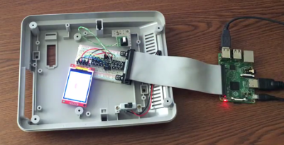
While waiting for some more parts to arrive I decided to work on the Reset switch functionality. I decided that I want to have the Reset switch control the backlight of the secondary screen. One press to turn it off, another press to turn it back on, etc. After some searching I wrote a simple Python script to detect the button press and shut off the backlight. Below is the script, with my comments, in case anyone else wants to do this and learn from how I did it. (If there are better ways to go about doing this, I'm open to hearing about it.)
#!/usr/bin/python

import RPi.GPIO as GPIO
import time

# set up BCM GPIO numbering
GPIO.setmode(GPIO.BCM)

# turn off warnings
GPIO.setwarnings(False)

# tell the script that we're going to output data on GPIO 23
GPIO.setup(23,GPIO.OUT)

# tell the script we're going to use GPIO 27 for input and act as a pull up resistor
GPIO.setup(27, GPIO.IN, pull_up_down=GPIO.PUD_UP)

# the default state of the light is on
light = 1

# run this unless there's an exception
try:

	# Turn ON Backlight by default
	GPIO.output(23,GPIO.HIGH)

	# do this forever
	while True:
		# use interrupt to wait for button to be pressed
		GPIO.wait_for_edge(27, GPIO.FALLING)
		# if the light is on, turn the light off
		if light == 1:
			#Turn OFF Backlight
			GPIO.output(23,GPIO.LOW)
			#change the state of the light variable so the script knows the light is off
			light = 0

		# if the light is off, turn the light on
		elif light == 0:
			# Turn ON Backlight
			GPIO.output(23,GPIO.HIGH)
			#change the state of the light variable so the script knows the light is on
			light = 1
		# wait a little while to account for bounce in the button
		time.sleep(0.2)

# keep running unless you Ctrl+C to break out of it
except KeyboardInterrupt:
	# reset the GPIO pins used in this program
	GPIO.cleanup()
I soldered up some test wires to the switch and connected it to my breadboard and things seemed to work. That was encouraging. The next step was to cut out just the corner of the board (Tip: tin snips work great for this) because the Pi won't fit with the SNES main board in place. The board was going to have to be taken apart to get the cartridge slot off anyway, so while I didn't like crunching through a little piece of history, it's in the spirit of giving this console new life.
I reconnected the switch to my breadboard and the switch seemed to be malfunctioning. The backlight kept turning on and off and from what I could tell the script was detecting that the switch was constantly being pressed. By this point it was almost 1 AM, so I went to bed to work in it again before work in the morning.
I decided to remove the switch from the remaining piece of the main board to see what was going on. The "top" two pins are just a piece of wire that are there to anchor the switch to the board. The bottom left pin of the switch and bottom right pin are two separate pieces of metal inside that are normally a closed switch and when you press the button the connection is opened. When I connected just the switch, disconnected from the board, up to my breadboard, things were fine. This led me to think I may have damaged the board, or that pins were connected within the board itself.
With the switch still off the board I did a little testing with the multimeter and I found that the "bottom left" pin is the only one that is isolated from the rest of the board. The other three pins are all grounded back to the board, including that big metal band on the perimeter.
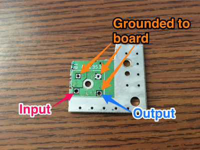
That was really good to know. I think that my problem was that when I connected the switch previously and it went haywire I must have had my wires backwards and connected the input pin to the ground part of the board and something shorted. Now that I know way more about Super Famicom Reset switches than I ever thought I would want to, I put the switch back on the board and connected two wires up, the signal wire (input) to the bottom left and the ground wire to the bottom right.Connecting it back up to the breadboard worked! I'm sure a lot of my headaches were because I'm inexperienced, but I learned how to troubleshoot a lot during this and also got to work on my soldering skills.
Here's a short video of the switch controlling the backlight.
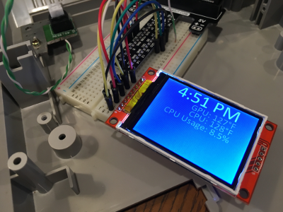
I'm going to look into a more advanced script that will cycle between the light on or off and also switching between the game art or some Pi information (Temperature or something like that) but I have to learn some more Python…
[Edit: Updated code to use interrupts instead of input state monitoring to be more efficient and use less CPU]
[Edit 2: cleaned up if statement] -
Good work; especially on the reset switch - I'm on version 2 of my build and I'm yet to get the reset switch functional.
I've only just joined and plan to post full details of my build but this caught my eye so had to comment here first. I used a custom PCB to interface a Pi0 in an effort to avoid the usual mess of wires - here's a taster:
-
@jackal123uk Very nice. I'm still amazed by people who make custom PCBs. That's a skill I've not developed and wouldn't even know where to begin. Heck, I'm still trying to figure out where I can print out a label for the cartridge once I'm done with it.
-
@obsidianspider Thanks; just posted the full saga of my build:
https://retropie.org.uk/forum/topic/3874/my-snes-buildTo be honest, I'm using the project as bit of an education, learning as I go. I designed the PCBs with a nifty (not to mention free) online tool over at upverter.com and had them fabricated at a reasonable cost over at oshpark.com - nothing much to it really.
-
In searching around I found a better way to poll for a GPIO event (using MUCH less CPU) so I updated the script above. I also have started playing around with displaying system information on the screen.
-
@obsidianspider said in Pi in a Super Famicom Build:
Heck, I'm still trying to figure out where I can print out a label for the cartridge once I'm done with it.
It's quite simple. Buy some label paper to print your cartridge-label. Or, i'll do it for you if you can't find a way to do it yourself, just need to check the costs of mailing it to you.
-
@Morph-X I may take you up on it when I get that far if I can't find a local shop to do it. I have a black and white laser printer, not a color one, and I don't want to spend hundreds of dollars on a printer just to make one label.
-
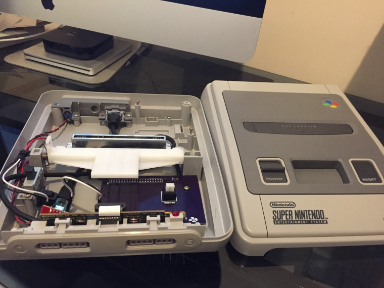
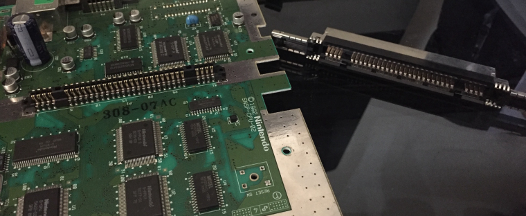
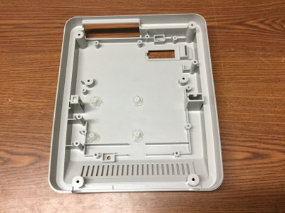
While waiting for some parts to arrive I decided to remove the pieces from the Super Famicom main board that I intend to reuse: the power switch socket, the controller ribbon cable jack, the power input jack (so I could get the back plate off the PCB, hopefully I can model it for a 3D print sometime in the future), and the game cartridge slot.
I learned today that desoldering components, especially ones with multiple pins is a skill I have yet to acquire. I got very frustrated, it took forever, and after many YouTube videos, a botched attempt with a heat gun, and finally just slowing down, taking my time, and not looking for a quick way to do it, I got the parts off the board.
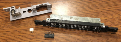
Unfortunately, the attempt to desolder the game cartridge slot from the board with a heat gun was a failure. I melted some of the plastic and it just plain didn't work. I ended up prying the metal housing (which had black marks on it when I got the Super Famicom) free from the board, and then desoldered each pin individually from the board, then reassembled the socket.
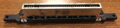
I took the game cartridge socket off the board because after my experience with cutting the board to get the Reset switch I knew I'd potentially cross connections in the board. I've tried inserting a game and removing it a few times and the pins don't seem to move, but since the pins aren't connected to a board at all, I can see them potentially working free. I don't plan to remove the game cartridge much, if ever, but I'm tossing around the idea of securing the pins either to a blank circuit board or maybe use hot glue. I don't love the hot glue option in case I would need to redo something, but I could put it in the valley underneath and it wouldn't look too messy.
The good news is that even though I melted the plastic a bit, once everything is assembled you'll never see it. I don't like that I made a mistake, but I'm new to this and there are certainly worse ways to make a mistake.
Onward!
-
@obsidianspider said in Pi in a Super Famicom Build:
I learned today that desoldering components, especially ones with multiple pins is a skill I have yet to acquire. I got very frustrated, it took forever, and after many YouTube videos, a botched attempt with a heat gun, and finally just slowing down, taking my time, and not looking for a quick way to do it, I got the parts off the board.
This is identical to my experience; reassuring to know it's not just me. I haven't even attempted the cartridge slot yet - far too many pins! Interestingly, on my European SNES the bulk of the cartridge slot can be pulled off the main board as it's on another socket.
In my build I could solder wires directly to the underside of the cartridge slot but that doesn't go with my neat, tangle-less vision.
-
@obsidianspider said in Pi in a Super Famicom Build:
Unfortunately, the attempt to desolder the game cartridge slot from the board with a heat gun was a failure. I melted some of the plastic and it just plain didn't work. I ended up prying the metal housing (which had black marks on it when I got the Super Famicom) free from the board, and then desoldered each pin individually from the board, then reassembled the socket.
That sounds like a lot of work. I used a dremel to chip away bits of the circuit board to isolate the pins for my usb stick in cart setup.
-
Hey guys, first post here. Super impressed by all the projects!
Im also doing a Snes build with my new Pi 3b.
(Built a bartop arcade last month, will be posting it in the forums as soon as I put on the new vinyl-art.)
Anywho, Im having a hard time googling the power button options. Iv read a lot about the powerblock way.
But is it in any way possible to attach the org powerbutton from the SNES directly to the Raspberry Gpio pins, to make a on/off solution? (I always "soft" shutdown through ES). If not, i might just use my Micro-usb cable with a rocker and sort of Macgyver it with glue to the Snes power button. Will be posting progress as soon I get the thing together.
Sorry for jacking thread. Pls delete if its against rules..
Thanks for your help, in advance / Mattias -
@jackal123uk I noticed quite a few board differences between Japan, American, and European boards. Over time even systems in the same region had board changes. Lucky you that the cartridge slot came right off.
-
Today's adventure in desoldering went much better than yesterday. I'm still by no means good at it, but I'm getting better.
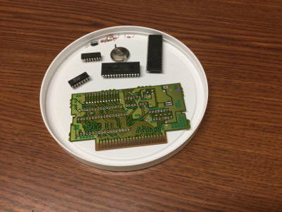
I successfully removed all the components from the J.League Excite Stage '96 game that will be the donor for my secondary screen. This blog post by Gabriel Torres had a lot of good tips on desoldering, but the one that seemed to help the most was to add some solder to each pin before you try to remove it.
What I started with:
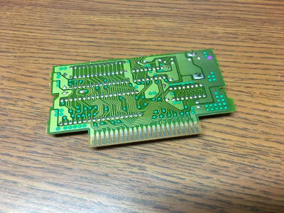
The end result. MUCH better than the hacked up mess I had yesterday.
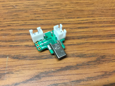
Since I was in a solder-y mood I decided to add JST jacks to my Reset button and Mausberry circuit.
I had to make small jumpers and hot glue the jack to the Reset button, but I think it turned out ok.
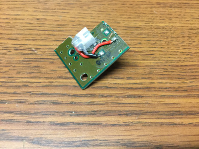
I want to try to keep things neat, so I put jacks on the bottom of the Mausberry for power and also for the GPIO. Ideally I'll be able to power the Super Famicom LED from the Raphnet USB adapter I ordered, so I don't mind blocking that with the socket.
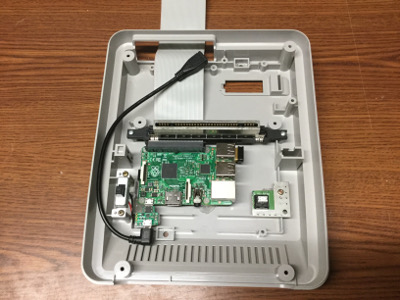
While I was working on things the standoffs I ordered came in the mail so I was able to attach those to the bottom of the case. It's probably too much hot glue, but I don't want anything moving.
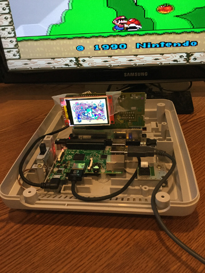
After putting the Pi in its final location I determined that I definitely won't be able to use the eject mechanism, but I'm ok with that. All in all, it was a good day.
-
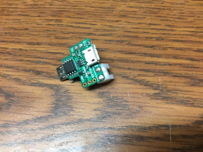
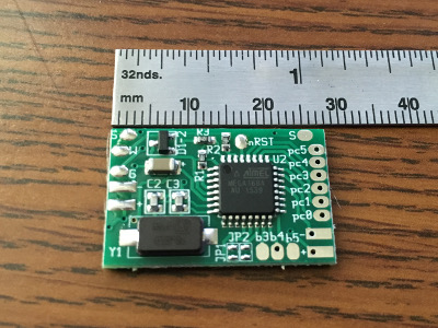
My Raphnet BRD-4NES4SNES adapter arrived and wow, this thing is tiny. The dimensions were listed on the website when I bought it, but seeing it in person makes me wonder how I'm going to mount it, and I really hope I don't mess anything up when soldering.
-
@obsidianspider remember to wire up your player 1 controller port for a multitap as well (yes on the 4nes4snes you have to put it on player 1)
-
@edmaul69 How did you do that? I've never owned or used a multitap.
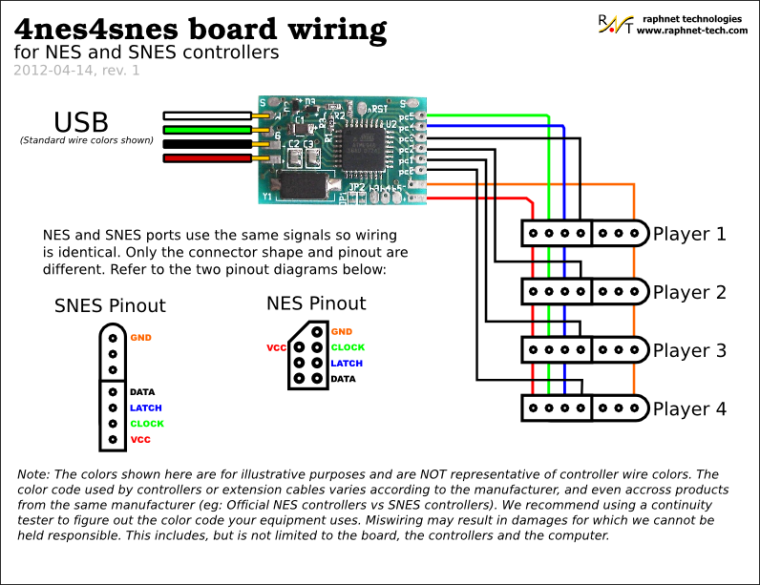
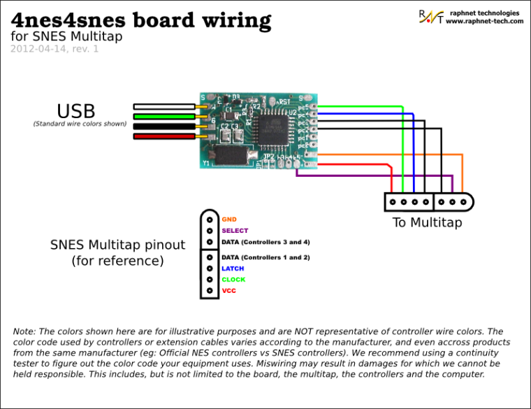
Based on the diagrams from Raphnet, it looks like Pin P3 is for Player 1 data and Pin P2 is for Player 2 data.
For multitap wiring it shows that Pin P3 is player 1/2 data and Pin P2 is for Player 3/4 data.
Did you just wire up the
SelectandDATA (Controllers 3 and 4)pins for the Player 1 controller in addition to the "normal" wiring? Essentially just two extra wires.
-
@obsidianspider just wire up the first two players wires how they are described. The multitap uses the other two unused pins. One of them shares a wire with player two. The other goes to its own solder pad on the chip. Having that wired up if you ever want to play more than two players you can. There are a lot of multitap games for the super nintendo and several for the nes.
-
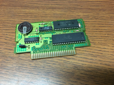
I'm still a bit intimidated by the Raphnet adapter, so last night I decided to figure out the pins on the game cartridge board and solder on a ribbon cable. I also removed the pins from my TFT and attached a cable. To keep things easier to take apart in the event of the screen breaking I added JST connectors between them.
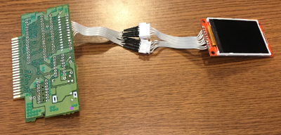
I then translated the GPIO pins to cartridge slot pins and soldered the ribbon cable on to each pin individually. I didn't attempt to solder to the pins while they were in the connector, I just pulled them out and then put them back in when I was done. When I went to test things out the screen was going crazy and I am pretty sure it was because when I smooshed the wires down when I screwed in the connector that some pins were touching. To keep things from shorting out I desoldered all the pins and then reattached them and used shrink wrap on the ends.
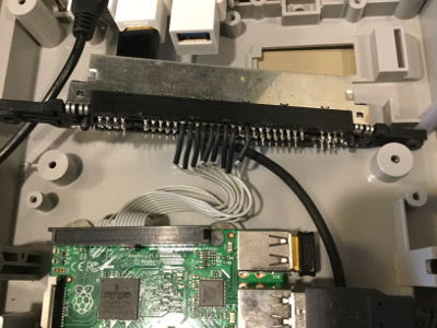
With the screen working in the cartridge slot I decided to connect the Mausberry to GPIO and the power switch to try it out. Things didn't go well. My bright idea of using JST connectors to make the switch easy to swap out if something breaks was a problem because the cables were pinched and broke off. I decided to just solder the Mausberry to the power switch and to the GPIO ribbon cable. Now everything is working correctly with the Mausberry.
I'm still unsure about cutting the cartridge for the screen, because it will depend on the label art I come up with, so for now I have it mocked up.
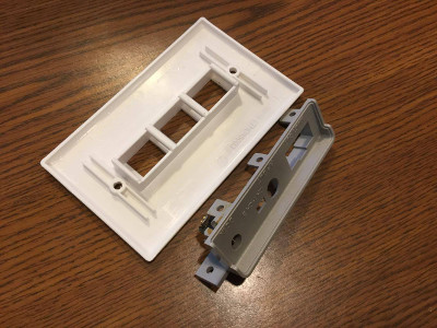
My mockup with a 3-port keystone jack plate showed it'll work.
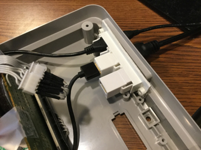
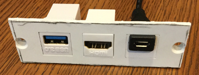
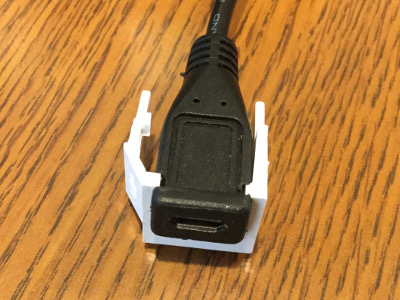
I wanted to try to use keystone jacks because they're a standard size, and there are all sorts of connectors, so I got one for HDMI and another for USB (in case I need to plug in a keyboard). No one makes a Micro USB keystone jack, so I notched a keystone jack blank and notched the right angle cable I'm using inside the case and it works well. No glue required.
A friend of mine has a 3D printer, so we're going to work on making a power plate with provisions for keystone jacks this weekend.
Contributions to the project are always appreciated, so if you would like to support us with a donation you can do so here.
Hosting provided by Mythic-Beasts. See the Hosting Information page for more information.