Pi in a Dreamcast VMU Build - WIP
-
@ABrugsch Thanks for the tips! I have a bunch going on this weekend, but if I get time to take a VMU apart, I'll be sure to post up what I find regarding test pads, etc.
-
I'll be playing on tuesday night (my hackerspace night) assuming I'm not spending the whole time desoldering DS lite Slot-2 cartridge ports! (I'm doing a roaring rade in them now...!)
and that the whole space isn't in disarray because of a large storage project going on. -
I took apart one of the VMUs on my lunch break today. I took a load of pictures, but this teardown at iFixit does a really good job of explaining things, so I won't reinvent the wheel here.
I wanted to see if I could use the tiny speaker from the VMU right off the Pi's GPIO, so I tried using the Adafruit Pi Zero PWM Audio guide to enable PWM. Since I'll be using Retrogame, I just used the image that I had already set up for my Burger King build. Unfortunately I got crazy boot errors.
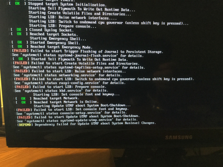
Since I was really just trying to see if PWM worked, I put a fresh image on the SD card, set the dtoverlay, and then, well, no sound.
I knew these speakers are tiny, and generally low quality, so I decided to see if the GPIO just wasn't powerful enough. I wired it up to the amp that's powering the speaker on my GBA build, and even with things cranked up, it was really quiet. The VMU speaker is effectively out.
If can't get sound to work on this tiny thing, it won't break my heart, but once parts show up, I'll see if I can cram a tiny Adafruit I2S amp and speaker in the case along with everything else.
-
@obsidianspider did you take the metal disk out of the casing? They make practically no noise without some form of casing round them to amplify it a bit
want to get a tft into your project, look no further than here https://retropie.org.uk/forum/topic/7464/ili9341-tft-screen-guide
-
@moosepr Yeah, it was out of the case, but even with my hand cupped around it, and plugged into the 2.5W Adafruit amp, it was still really quiet. If I'm going to have to run an amp anyway, I might as well get a speaker that;s more than a piece of brass with a blob of solder on the back of it.
-
@obsidianspider Yeah it's never going to replace your HiFi, but back in the proper casing it will get louder (that's the magic that gives you musical birthday cards)
They are actually a thin later of peizo crystals that make the disk flex when voltage is applied
-
Yeah, piezos need casing. I could never understand why my watches in the 80's didn't make a sound when i took the piezo out of its holder...
-
@ABrugsch I'll see how things all fit in the case, but I have a feeling that area normally used as a "speaker box" will need to be ground down so it can be filled with battery.
-
I have the same feeling but hope i can maybe 3D print something that works better
-
@ABrugsch 3D Print a whole case? Kind of defeats the purpose of putting it in a VMU shell, no? Or just a speaker box for inside?
-
surface mount piezo's can be pretty small, and are all self contained
http://uk.rs-online.com/web/p/piezo-buzzer-components/6198456/
12x12x3mm could maybe squeeze one in somewhere
want to get a tft into your project, look no further than here https://retropie.org.uk/forum/topic/7464/ili9341-tft-screen-guide
-
@moosepr Is that the type you used in your build where it was running directly off GPIO? How did you go about enabling that sound? You said it was quiet, but "loud enough" I believe. I only briefly messed with it, but the "easy" way that Adafruit listed about updating
/boot/config.txtmade the whole system puke, and I am sure it's because it was conflicting with Retrogame. Since Retrogame is a must (gotta be able to use the buttons), I'd have to look at another way to enable PWM sound and still have Retrogame work. -
@obsidianspider i had it with retrogame and the sound on, i even had the same pin in retrogame, as does the pwm sound!! pin13 was set as one of my direction buttons, and is the default second output for the pwm audio. didnt have any issues though. your messages were weird, didnt really mention anything related to either.
as for the volume, im not one for loud noises, so what might seem acceptable to me might be barely audible to someone else. the missus was complaining about the noise from the other side of the room, so it cant be too bad?
all i did to get it working was add into /boot/config.txt
dtoverlay=pwm,pin=18,func=2to get the mono sound. I used raspi-config to ensure the pi was forcing sound to the '3.5mm' and cranked it up to the max with alsamixer
-
@obsidianspider said in Pi in a Dreamcast VMU Build - WIP:
@ABrugsch 3D Print a whole case? Kind of defeats the purpose of putting it in a VMU shell, no? Or just a speaker box for inside?
Was just thinking a frame but moose's smd piezo might be a better shout anyway. BTW @moosepr your picb-tft was getting some admiration at a hacksoton today (a southampton hackathon nerd fest)
-
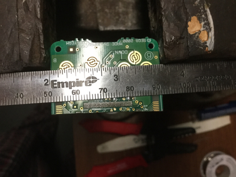
Thanks to someone taking the forum offline this morning, I was working in the garage most of the day on this VMU stuff. I managed to find that only
UpandDownhave test pads, but I did find which pins on the chip correspond to which button.Button Pin ------------- Up 25 Down 26 Left 27 Right 28 A 29 B 30 Mode 31 Sleep 32The problem I had was that I couldn't manage to attach wires to the really fine pads on the PCB.
I decided to try to scratch my own test pads on the board, but that ended up not working well when I tried to attach a wire, and due to flux being on the board, and me not being as careful as I should have been, solder flowed over the carbon pad contact. I tried finishing, but the carbon pads just didn't work. Luckily I had another VMU to use.
Having learned from the first attempt, I was more careful and managed to get leads connected up to the board.
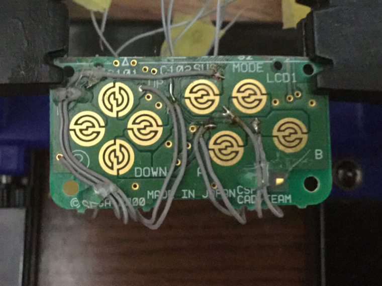
Using Retrogame I found that things worked, but I found that
LeftandUpweren't registering quite right, and were hard to press. I rerouted the cables a bit and it was much better. I also see that theSleepbutton doesn't stick out as far from the case asModeso it's not as easy to press, but considering that you don't really pressSelectmuch during play, it's fine. I will likely tweak things more when I get more parts in, but I'm happy with how things are working, even if I did learn a $6 lesson in patience this morning.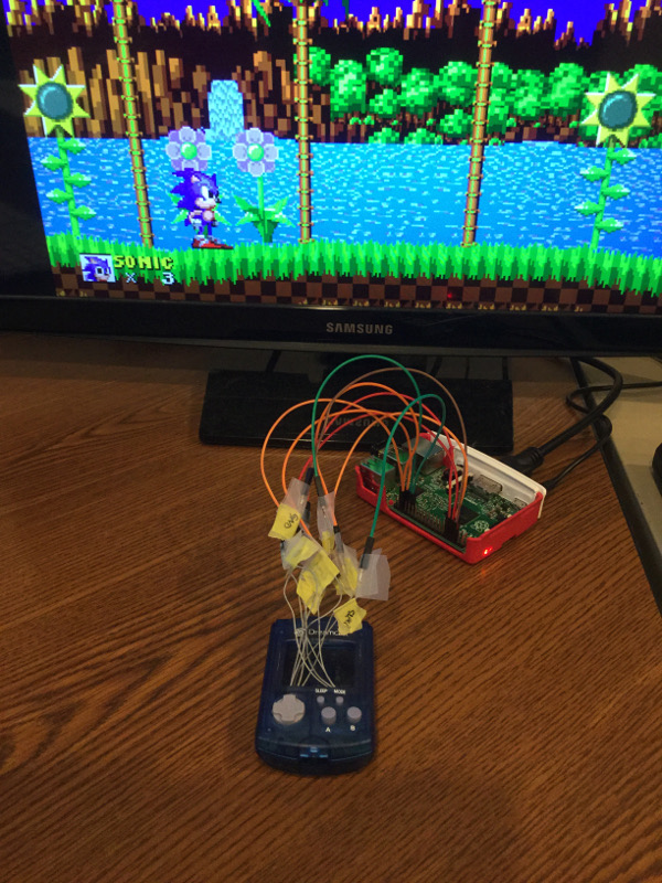
-
@obsidianspider awesome job! Those pads will probably still work covered in solder. Will maybe oxidise faster though I guess
-
@ABrugsch nerdfest! Ha ha I should sell them!
-
@moosepr said in Pi in a Dreamcast VMU Build - WIP:
dtoverlay=pwm,pin=18,func=2Your method worked! I'm not sure why my earlier attempt at using the overlay from Adafruit and only using one channel caused it to fail, but I only wanted mono anyway, so your solution was better. It's quiet, but loud enough I guess. Still not sure if thing will fit with the stock piezo and shell, but it opens the door to that small SMT one you mentioned. Maybe attach leads to it and glue it to the case?
Here's a little test video.
-
@obsidianspider wooohooo! It's amazing how much difference that casing makes
want to get a tft into your project, look no further than here https://retropie.org.uk/forum/topic/7464/ili9341-tft-screen-guide
-
@moosepr Given that these piezos like something to resonate, do those SMT ones need to be soldered to a board, or do you think I would be able to get a decent result from soldering up leads and then gluing it to the case itself? I don't see me creating a custom PCB for this. At least this iteration.
Contributions to the project are always appreciated, so if you would like to support us with a donation you can do so here.
Hosting provided by Mythic-Beasts. See the Hosting Information page for more information.