Pi in a Dreamcast VMU Build - WIP
-
@obsidianspider hmmm are those the 128x128 screens, or the 128x160?
-
@moosepr they're the "red board" screens.
Setting the HDMI resolution to 128 x 128 in
/boot/config.txtdidn't help.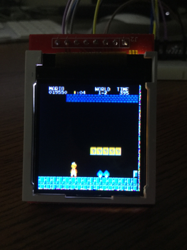
Great refresh rate though. Very smooth.
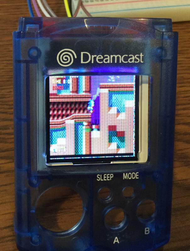
@lilbud The whole screen shows. I'm going to actually end up coloring in the white surround black to hide it a bit. This is just "set in" but you get the idea.
-
@obsidianspider just for shits and giggles, try running it with the other driver
options fbtft_device name=fb_st7735r gpios=reset:25,dc:24 speed=40000000 bgr=1 rotate=0 custom=1 fps=60
then if that works, try adding some size in there
options fbtft_device name=fb_st7735r gpios=reset:25,dc:24 speed=40000000 height=128 bgr=1 rotate=0 custom=1 fps=60
all in sudo nano /etc/modprobe.d/fbtft.conf of course
-
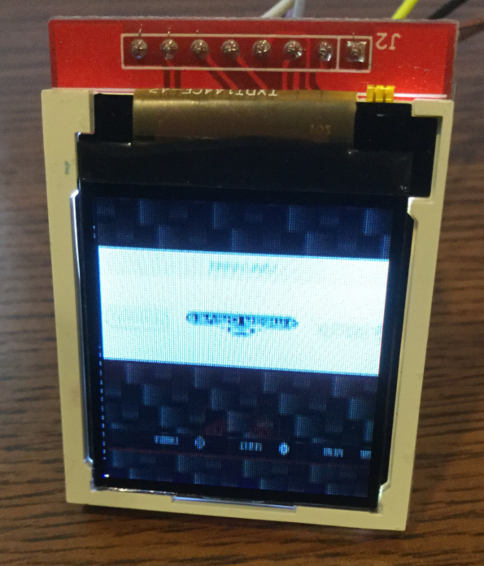
@moosepr That gave me a different kind of garbage. The bad pixels moved to the other side, things are upside down, and the bottom output is garbled.
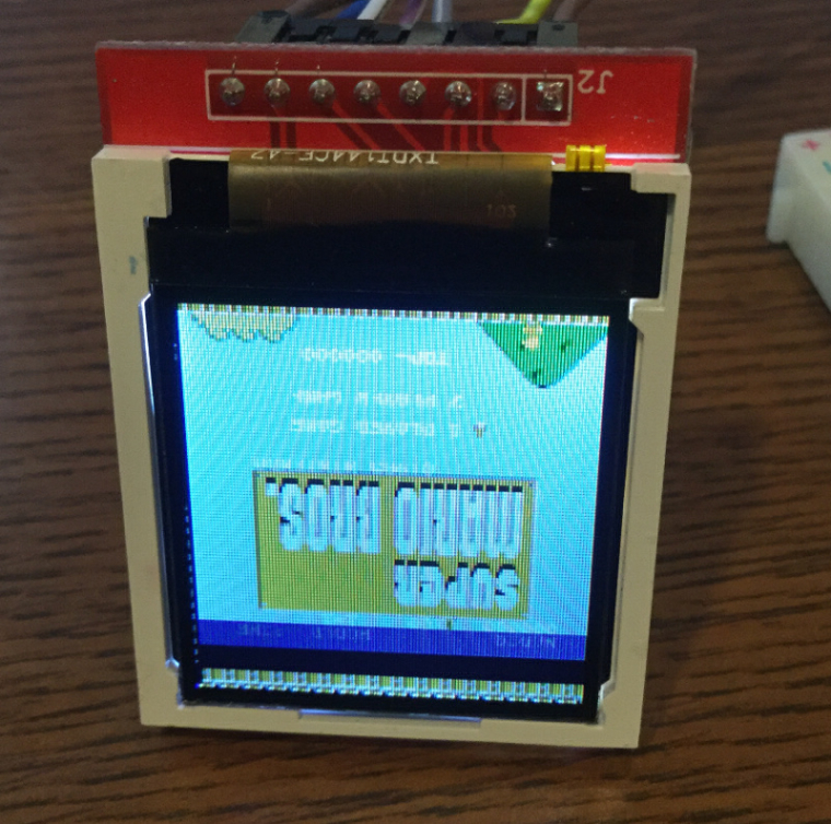
-
@obsidianspider odd!! it behaves differently to the one i have got. Although mine is probably wired differently (you may also have a totally different screen on the board)
notro did point me in the direction of using the flex driver, where you can basically set the full init commands. I did start looking, but decided to wait till my boards arrived (they have literally just been marked as shipped!!)
here is all i know so far https://github.com/notro/fbtft/issues/453
-
@obsidianspider Mine have H144TC215A-V0 on the ribbon
-
I went back to the ILI9163 driver and then tried messing with some overscan settings, which didn't seem to help once EmulationStation loaded, but I do see that the garbled text appears to be from the console, so that may be an insight into what's going on.
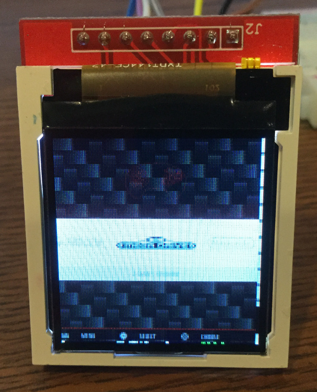
I'm going to have to mess with it. Like I said, I want to make this stuff works before I go removing things from the board. ;)
-
@moosepr Mine say TXDT144CF-47 on the ribbon
-
@obsidianspider yours seems to have a few more pins than mine internally i think (although the search is a bit of a minefield)
i think the garbage is generally just leftovers from stuff that has been on the screen on other boots. from a cold boot it will be rainbowsnow, from a setings change and a reboot it will be whatever was there last time
-
@moosepr I can confirm the rainbow snow from a cold boot. I can also confirm that the other screen behaves the same way. Initially it only had garbage on the right, but now it has garbage on the bottom and right, so it's consistent. I need to shift things down and to the right. Weird.
-
@moosepr Ideally I'd like to be able to set overscan like on the 3.2" TFT I'm using so I can keep the image from displaying at the top of the screen where it's covered by the VMU plastic. Though, in looking through it, I have that one set up differently.
@obsidianspider said in Pi in a Gameboy Advance Build - WIP:
My SainSmart 3.2" TFT showed up today and getting it to work wasn't as straightforward as I initially read, but it was totally doable and the speed seems very good when connected to my test mule Raspberry Pi 2 with a fresh image of RetroPie updated to 4.0.6.
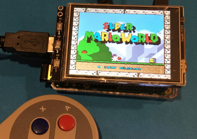
(I still have the protective film in place)OK, so here's how I got the screen working on a freshly installed image of RetroPie 4.0.6 on a Raspberry Pi 2. Steps are a combination of a few posts here and on GitHub
First I added the following to the bottom of the
/boot/config.txt#Waveshare 3.2 TFT Screen #same resolution for hdmi and tft hdmi_force_hotplug=1 hdmi_cvt=320 240 60 1 0 0 0 hdmi_group=2 hdmi_mode=1 hdmi_mode=87 dtparam=spi=on dtoverlay=waveshare32b:rotate=270,speed=82000000,fps=60Then I rebooted and wondered why nothing had happened. It turned out I needed to install the device tree overlay (that's what
dtoverlaymeans, you learn something every day). Since RetroPie isgit clone https://github.com/swkim01/waveshare-dtoverlays.git sudo cp waveshare-dtoverlays/waveshare32b-overlay.dtb /boot/overlays/waveshare32b.dtbo -
@obsidianspider yeah I think the overscan basically just shrinks the image within the screen area, so we need to remove the rainbowsnow before the overscan can be used properly.
I think the init sequence needs tweaks to get the image starting in the correct place. I was going to start off using the link notro sent to me, and compare that against the init sequence within the driver code itself. Then once that was working, get the data sheet and see which registers can be tweaked
-
@moosepr That makes a lot of sense. I need to run some errands, but I'll see what I can figure out tonight, if anything. Thanks again for assisting with this.
-
@obsidianspider Not a problem! I need to fix it too! :p
-
I realized that when I was playing with things, I put the following in the
/boot/config.txtto get the 128x128 working at the right resolution. I'm not sure if this is better or worse for the garbage pixel problem (probably not affecting it)hdmi_force_hotplug=1 hdmi_cvt=128 128 60 1 0 0 0 hdmi_group=2 hdmi_mode=1 hdmi_mode=87I basically just took what I did for the Waveshare screen and adjusted it. Games are playing in the correct aspect ratio (I actually have a black bar at the top and bottom when playing a game), but EmulationStation DGAF and just takes up the whole screen.
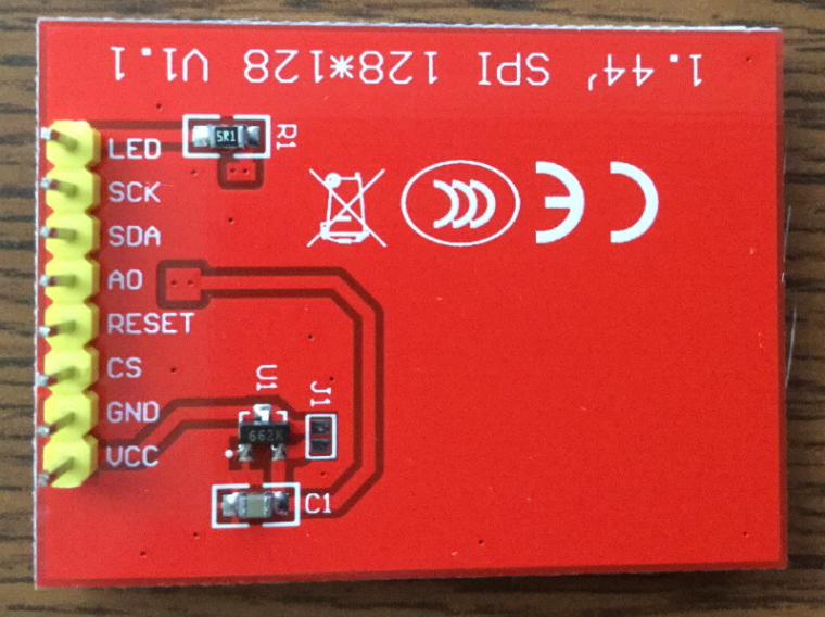
To try to help with identification and troubleshooting, I pried one of the screens away from the board.
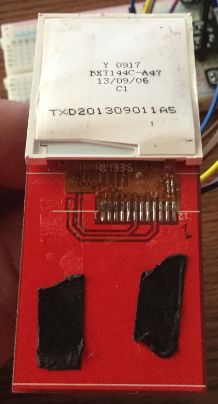
-
Since this screen stuff appears to be a driver/software issue, I'm thinking about removing the screen from the board, making sure it works as well as it did when on the board, then fitting it to a VMU so I can try fitting a Zero in with it. The software stuff can be tweaked really any time. What say you, hive mind?
-
@obsidianspider you actually have less pins than my screen!! the pcb is really simple on these, you could just grind all the excess off and end up with something pretty tiny
-
@moosepr So you're suggesting I shouldn't remove it from the board? It's almost as if there aren't any instructions on how to do this kind of stuff. :-P
-
@obsidianspider well you could solder direct to the ribbon. Its not drasticly difficult, you could quite easily trace out the circuit, the 4 data pins will be going directly to the screen pins, there will be a 10k resistor for the backlight and probably a 3v regulator going to vcc (although it will be happy with 3.3v from the pi)
im struggling to find anyone selling a naked 1.44" screen with just 12 pins. the ones i have are 13 pins ones, although the 13th pin is not connected on the 'module schematic' listed here
https://www.elecrow.com/144-128x-128-tft-lcd-with-spi-interface-p-855.html -
@moosepr I'm only into these things $7 total, including shipping for both, so if I cook one or have to put them in the parts bin, it won't kill me, but I'm not certain how I could be sure ordering another screen wouldn't have the same garbage pixels issue.
Contributions to the project are always appreciated, so if you would like to support us with a donation you can do so here.
Hosting provided by Mythic-Beasts. See the Hosting Information page for more information.