RetroPie forum home
    • Recent
    • Tags
    • Popular
    • Home
    • Docs
    • Register
    • Login

    Pi in a Dreamcast VMU Build - WIP

    Scheduled Pinned Locked Moved Projects and Themes
    buildprojecthandheldvmudreamcast
    157 Posts 7 Posters 94.2k Views
    Loading More Posts
    • Oldest to Newest
    • Newest to Oldest
    • Most Votes
    Reply
    • Reply as topic
    Log in to reply
    This topic has been deleted. Only users with topic management privileges can see it.
    • obsidianspiderO
      obsidianspider @celly
      last edited by

      @celly

      πŸ“· @obsidianspider

      1 Reply Last reply Reply Quote 0
      • obsidianspiderO
        obsidianspider
        last edited by

        Thanks to @celly I now have some really nice white VMUs coming my way.

        The plan now is to figure out how to do this with one of the blue ones, then do it "for real' with a white one.

        πŸ“· @obsidianspider

        mooseprM 1 Reply Last reply Reply Quote 0
        • mooseprM
          moosepr @obsidianspider
          last edited by

          @obsidianspider the white ones do have the Best look! I don't have the flair/time/patience for case modding though. Still have a GBA shell stripped and ready for the slaughter

          want to get a tft into your project, look no further than here https://retropie.org.uk/forum/topic/7464/ili9341-tft-screen-guide

          1 Reply Last reply Reply Quote 1
          • A
            ABrugsch
            last edited by

            So i got the big parts stripped off that charge board, replaced the big inductor with a more expensive, flatter wurth one. Since i was doing other stuff as well at the hackspace tonight (making up some DMG bivert boards) I didn't manage any testing :(
            Someone also sprung a free DS and DSi on me... :D
            Along with some really legit looking bootleg GBA pokemon carts.

            1 Reply Last reply Reply Quote 1
            • mooseprM
              moosepr
              last edited by

              i was messing in my parts bin and found a few of these

              http://www.ebay.co.uk/itm/371440045594

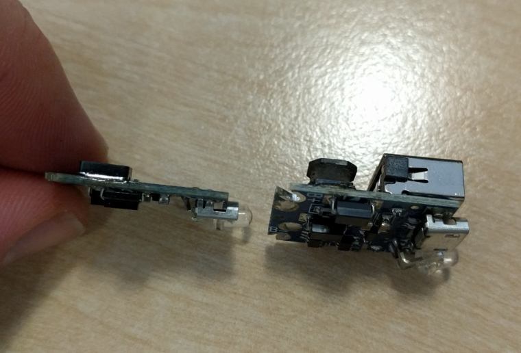
              the pcb at the end is actually really small. couldnt pry it out of the plastic while i was looking, but desolder the battery terminals and the usb socket, and it looks to be quite tiny!!

              want to get a tft into your project, look no further than here https://retropie.org.uk/forum/topic/7464/ili9341-tft-screen-guide

              A 1 Reply Last reply Reply Quote 1
              • A
                ABrugsch @moosepr
                last edited by

                @moosepr I think my board is actually meant for something just like that. this was linked at the bottom of that item:
                http://www.ebay.co.uk/itm/2600mAh-Battery-USB-Case-Kit-HOT-Bank-18650-DIY-Power-Box-For-All-Phone-Charger/291950546291

                1 Reply Last reply Reply Quote 1
                • A
                  ABrugsch
                  last edited by ABrugsch

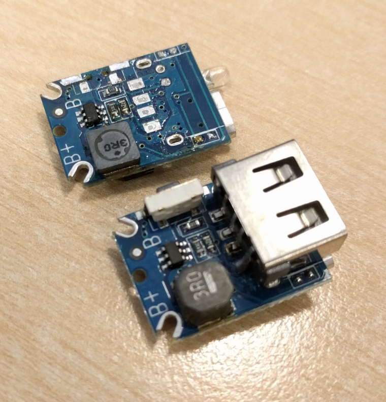
                  here's the reduced size charge/boost board:
                  removed the USB socket and flashlight switch, swapped the tall inductor for a flat Wurth one
                  0_1490801864700_2017-03-29 13.29.07-sm.jpg

                  0_1490801930899_2017-03-29 13.28.39-sm.jpg

                  obsidianspiderO 1 Reply Last reply Reply Quote 0
                  • mooseprM
                    moosepr
                    last edited by moosepr

                    @ABrugsch whats this? a boost board for ants?

                    what does the button on there actually do?

                    want to get a tft into your project, look no further than here https://retropie.org.uk/forum/topic/7464/ili9341-tft-screen-guide

                    A 1 Reply Last reply Reply Quote 1
                    • A
                      ABrugsch @moosepr
                      last edited by

                      @moosepr as far as i can tell, the switch JUST activates the flashlight LED (the big through hole one) so it's coming off. if it does anything else, I can always wire on a remote one. there are 2 0402 SMD LED's underneath it for status (so far just flash alternating red and blue with no battery attached)

                      1 Reply Last reply Reply Quote 0
                      • obsidianspiderO
                        obsidianspider @ABrugsch
                        last edited by obsidianspider

                        @ABrugsch When you remove a component that has through hole and surface mount parts to it, like that USB port, how do you go about it? Things like that kick my butt every time and I end up making a huge mess.

                        How did you go about replacing the inductor? It looks like all of the contacts are underneath it.

                        πŸ“· @obsidianspider

                        A 1 Reply Last reply Reply Quote 0
                        • A
                          ABrugsch @obsidianspider
                          last edited by ABrugsch

                          @obsidianspider it was a bit of a bitch tbh... The tall Inductor was in the way of the usb so that had to come off first... Bit of hot air, but not too much because of the surrounding stuff, bit of light prising with the hot iron but again not too much that the opposite pad doesn't lift. And just go back and forth til is comes off. Then the usb port i got lucky with as one side wasn't too well soldered and some wick got most of the through hole part. Then more flux and wick for the surface mount legs with some gentle prising with heavy tweezers.
                          This was pretty next level desoldering really! But then I'm a soldering ninja ;)
                          alt text

                          obsidianspiderO 1 Reply Last reply Reply Quote 1
                          • obsidianspiderO
                            obsidianspider @ABrugsch
                            last edited by

                            @ABrugsch If you've seen my cut down Pi 3, you'll notice that I am definitely not a ninja, but I'm working on it.

                            πŸ“· @obsidianspider

                            A 1 Reply Last reply Reply Quote 1
                            • A
                              ABrugsch @obsidianspider
                              last edited by ABrugsch

                              @obsidianspider said in Pi in a Dreamcast VMU Build - WIP:

                              @ABrugsch If you've seen my cut down Pi 3, you'll notice that I am definitely not a ninja, but I'm working on it.

                              It's not too bad really. Those ribbon sockets are super tricky to get off cleanly. My very first attempt at an A+ looks much worse than that... I'll get a pic...
                              Edit: check this https://www.hackster.io/abrugsch/mameboypi-ff2428

                              1 Reply Last reply Reply Quote 1
                              • obsidianspiderO
                                obsidianspider
                                last edited by

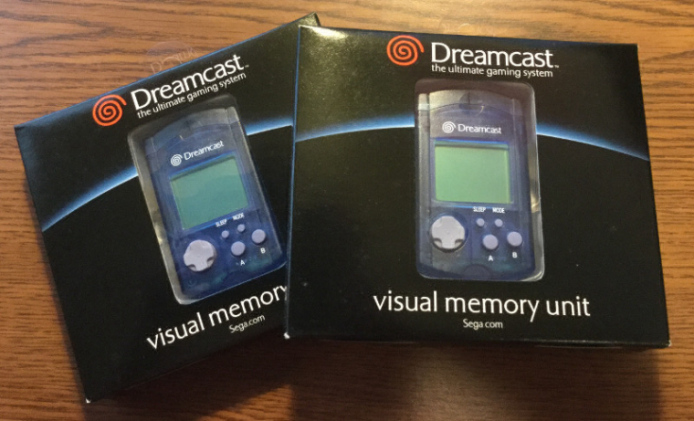
                                My blue VMUs arrived today. Brand new, perfect shape, and yeah, small. I know I read the dimensions on the Internet, but seeing one in person is different. I hadn't seen a VMU in real life in at least ten years, and wow, this is going to be interesting. Screens are still on their way over from China, but I can work on finding test points for the buttons and hope that there's some common grounding going on.

                                0_1490906048556_blue-vmus.jpg

                                πŸ“· @obsidianspider

                                mooseprM 1 Reply Last reply Reply Quote 1
                                • mooseprM
                                  moosepr @obsidianspider
                                  last edited by

                                  @obsidianspider I have that problem all the time! Design a PCB, see the components all zoomed in, think nothing of if, then I see those smd components arrive in the post, and I need a microscope!

                                  want to get a tft into your project, look no further than here https://retropie.org.uk/forum/topic/7464/ili9341-tft-screen-guide

                                  obsidianspiderO 1 Reply Last reply Reply Quote 1
                                  • obsidianspiderO
                                    obsidianspider @moosepr
                                    last edited by

                                    @moosepr At this point it's more of a sense of "how the heck am I going to do this?"

                                    I look at my Burger King toy and that thing looks absolutely massive by comparison.

                                    πŸ“· @obsidianspider

                                    mooseprM 1 Reply Last reply Reply Quote 0
                                    • mooseprM
                                      moosepr @obsidianspider
                                      last edited by

                                      @obsidianspider that's what she said :|

                                      want to get a tft into your project, look no further than here https://retropie.org.uk/forum/topic/7464/ili9341-tft-screen-guide

                                      1 Reply Last reply Reply Quote 0
                                      • A
                                        ABrugsch
                                        last edited by

                                        some helpful info @obsidianspider : the zero fits exactly between the screw posts :) perhaps some shaving required, but literally scrapings.
                                        the main pcb has screw mountings right next to the button pads so ideal for cutting down. I haven't tested for common ground etc but i don't think it'll be a problem with 4 buttons and 4 directions.

                                        The 1.44 128x128's take up less internal space than the original mono LCD, especially once you remove the carrier PCB.
                                        if you line up the uSD card to be at the bottom, you can cut out the lanyard post and surround and have a perfectly lined up hole for uSD access.

                                        obsidianspiderO 1 Reply Last reply Reply Quote 1
                                        • obsidianspiderO
                                          obsidianspider @ABrugsch
                                          last edited by

                                          @ABrugsch Thanks for the tips! I have a bunch going on this weekend, but if I get time to take a VMU apart, I'll be sure to post up what I find regarding test pads, etc.

                                          πŸ“· @obsidianspider

                                          1 Reply Last reply Reply Quote 0
                                          • A
                                            ABrugsch
                                            last edited by

                                            I'll be playing on tuesday night (my hackerspace night) assuming I'm not spending the whole time desoldering DS lite Slot-2 cartridge ports! (I'm doing a roaring rade in them now...!)
                                            and that the whole space isn't in disarray because of a large storage project going on.

                                            1 Reply Last reply Reply Quote 0
                                            • First post
                                              Last post

                                            Contributions to the project are always appreciated, so if you would like to support us with a donation you can do so here.

                                            Hosting provided by Mythic-Beasts. See the Hosting Information page for more information.