My SNES Build
-
The last outward facing blemish on my build is the backplate; I've completely reused the power jack and the HDMI connector fits nicely into the multi-out but the hole for the RF-out is a tad unsightly. I've had a blank black plate 3D printed with the intention of cutting the holes to suit but the finish was no where near good enough (although you can't see it in the photos.
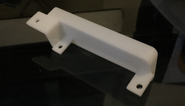
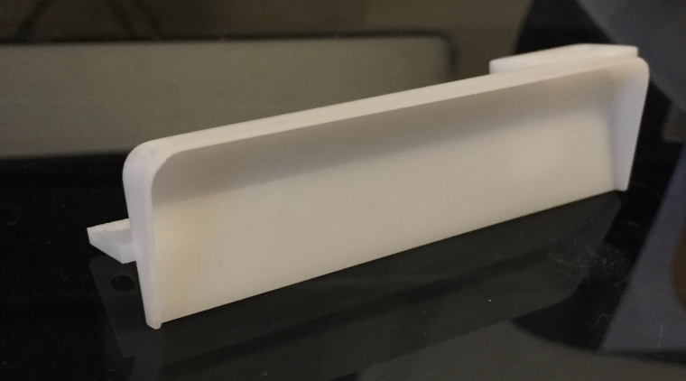
I can upload the 3D file somewhere if anyone is interested in doing something similar. -
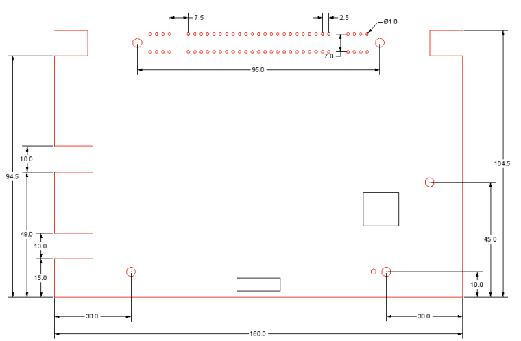
I'm turning my attention to the next version of my pcb, I've decided to go easy on myself for now and leave the USB hub contained in a cartridge although this means I've now to mount the 62 pin cartridge connector onto the pcb. Below are my measurements of the original board - I know the position of the reset switch and the mounting holes to the right are correct as I used these on the last version of my board. Anyone know if there's a more official version of this type of drawing or something that's at least been verified?
-
@jackal123uk said in My SNES Build:
I can upload the 3D file somewhere if anyone is interested in doing something similar.
Can you upload that STL file? A friend of mine offered to help me with making a 3D print of the back panel tomorrow, but if you already modeled it that will be a huge help. I want to adapt it to add in keystone jacks.
-
@obsidianspider of course, here you go, shouldn't be too hard to add the keystone jacks.
https://dl.dropboxusercontent.com/u/9389059/SNES backplate.stl
Also, not sure if there's any differences between the regions but at least it's a decent starting point.
-
@jackal123uk said in My SNES Build:
@obsidianspider of course, here you go, shouldn't be too hard to add the keystone jacks.
https://dl.dropboxusercontent.com/u/9389059/SNES backplate.stl
Also, not sure if there's any differences between the regions but at least it's a decent starting point.
Thanks!
-
OK so my day job's been getting in the way on this project for a while but I've just gotten back to it this weekend and trying to get USB hub to work over the cartridge slot. I've soldered directed to the pads for the USB data connections.
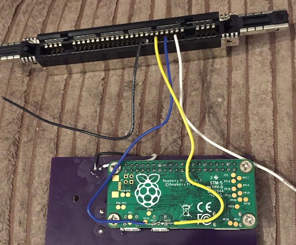
All in all I think the finished article looks good...
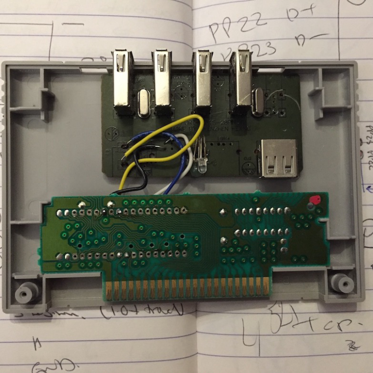
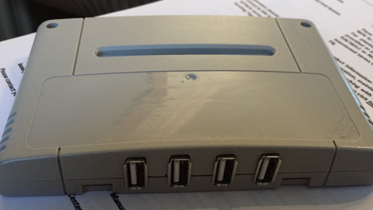
Only problem being the hub doesn't seem to want to work. I've tried crossing over the data pins in case I'd messed up there but nothing. Does anyone have any experience with doing something like this with a pi zero?
-
Are you supplying it with its own power? or power from the pi? I've heard pi zero are quit temperamental with power to USB hubs.
-
@monstermadeofman did you test the original wires before wiring this?? Red isnt always on 5v and green isnt always data, etc., etc....
-
@monstermadeofman no, not supplied through the pi zero, both the hub and the pi zero are fed from a common rail though. The pi runs fine but I'll try giving the hub a completely separate supply in case there are some problems there.
@edmaul69 the 5v and GND are certainly right, wasn't 100% on the data, hence swapping round to check.
-
@jackal123uk I can tell you, in dealing with my gameboy zero project, that the PI zero is extremely picky on hubs that work. Definitely power it from your 5V rail, not the pi. Also twist your D+ and D- lines together and keep them as short as you can... Inside your cart the wires are a mess so I'd definitely recommend shorting them and twisting them... Also you can try to drop the USB speed to v1.1 (which is ok for wifi, keyboards, and controllers). Do this by adding this to the end of your cmdlines.txt:
dwc_otg.speed=1
If you're bored, you can look through the forums at sudomod (where the gameboy zero project is). There is along thread on Helder's AIO board that talks about the usb issues....
-
@jsawhite Point taken about the data wires; I'll tidy those up.
Curiously, I've tried the same hub (I actually picked up two) directly in the Pi zero with an OTG adaptor and it's still not recognised, although works fine in a full sized Pi. Could it be something with the OTG protocol and hub rather that my sloppy wiring?
-
@jackal123uk it certainly can be the hub with a pi zero. You should jumper the 5v off of the power going in and not off the usb ports power.
-
I've tried a couple of different hubs now with no success through my cartridge connector hack job. Neither work connected directly to the pi by USB either.
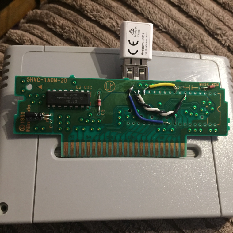
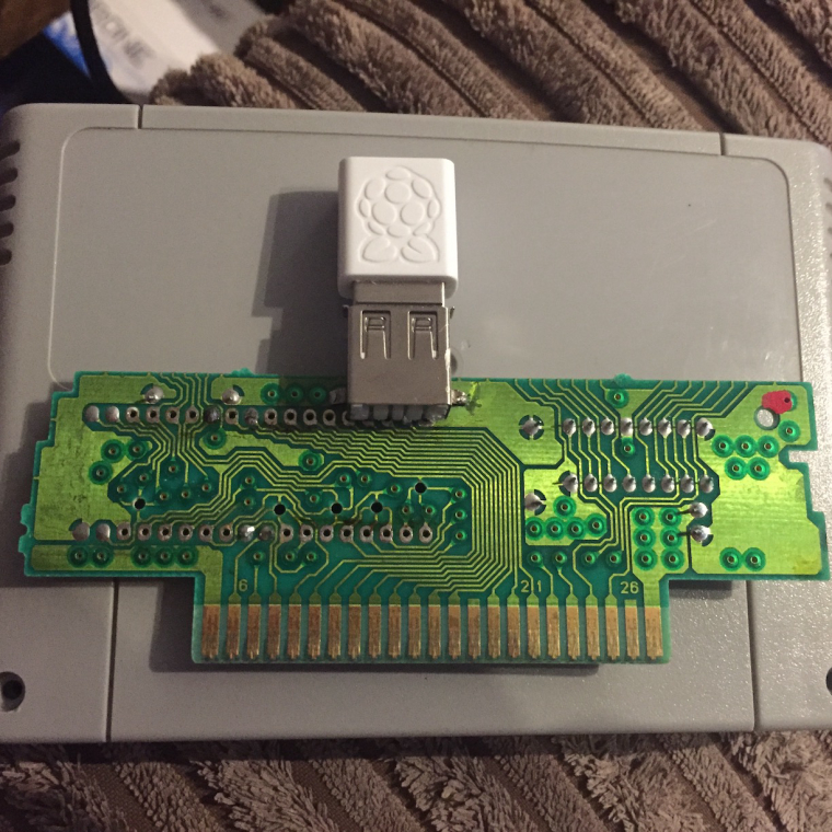
Just to make sure I wasn't going mad I connected a single USB port to to my cartridge adaptor and low and behold it works fine - at least I know my wiring's not to blame. Guess I'll need to pick up a hub that's confirmed to work with the zero.
-
@jackal123uk I've read in more than a few places that the Zero doesn't do well with powering hubs, but if you power the hub from the same 5V source as the Pi you'll have better results. To echo @edmaul69's comment about powering the hub, what might be worth testing would be to use the same hub that you were having trouble with, but instead of using the OTG power pins, use the 5V pins from the GPIO.
-
@jackal123uk i use the rockband usb hub. The one that has 4 usb ports in a row that is not self powered. The only issue i found is if you are going to set bluetooth or wifi you have to unplug every device except for that device and your keyboard. It wont accept you wifi password if you dont. It still may take 2-3 tries even if you do as i said. Even with a powered hub. The pi zero is kinda wonky with that.
-
@obsidianspider The supply to the cartridge connector has always come from the GPIO 5V pin so I'm not convinced it's a power problem.
I've just found a old hub that I had laying around (a Trust 4-port usb 2.0) and surprisingly it works. Incidentally it uses the GL850G controller which is different to the others I tried - maybe there's something in that. Anyway, it managed to connect to wifi and a wireless keyboard (which is probably the extent of my needs) with no problems. @edmaul69 I've not seen any issues like you describe but its still early days.
Best thing is I've found these hubs still available on eBay so I've got another couple on the way in case I mess up during fitting them to a cartridge.
-
Success! I've now got a working usb hub tucked away in a cartridge. Conveniently, one of the 4 available ports it internal allowing my to hide away a mini wifi dongle leaving 3 outward facing ports.
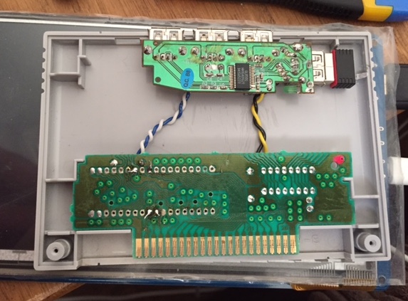
Next job is the cart label; as the cart is just an expansion to allow usb and wifi connectivity I'm thinking of something along the lines of this:

Although I think I might prefer a flatter Retropie logo to give the whole think a consistent look.
-
I received the latest version of my PCB this week (probably the last too; because it's priced by the sq. in. it's starting to get expensive the bigger it gets).
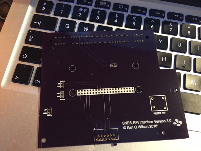
First of all I'm happy to report that the 62-pin cart connector pins perfectly so looks like my measurements were good! Yeah, I know, cleaning the flux is my next job.
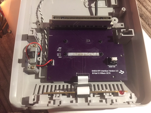
I gave up on the idea of incorporating a DIY shutdown circuit in the board (beyond my abilities), instead hid the Mausberry circuit underneath.
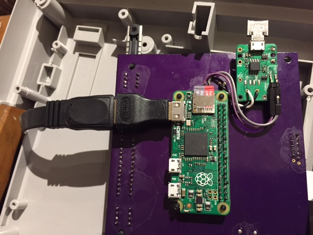
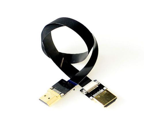
The HDMI plug is a little too fat, in the last version I trimmed it down with a knife but I'd prefer a more elegant solution, I'm looking at something like this but I can't find a mini male to a standard female version - I'll keep hunting.
-
@jackal123uk How about this?

-
@lilbud Thanks, I like that; that's definitely the RetroPie logo for the job. I'll get a few different designs printed up to see what they look like on a cart - that'll be the real test.
Contributions to the project are always appreciated, so if you would like to support us with a donation you can do so here.
Hosting provided by Mythic-Beasts. See the Hosting Information page for more information.