RetroPie forum home
    • Recent
    • Tags
    • Popular
    • Home
    • Docs
    • Register
    • Login

    Pi in a Dreamcast VMU Build - WIP

    Scheduled Pinned Locked Moved Projects and Themes
    buildprojecthandheldvmudreamcast
    157 Posts 7 Posters 91.0k Views
    Loading More Posts
    • Oldest to Newest
    • Newest to Oldest
    • Most Votes
    Reply
    • Reply as topic
    Log in to reply
    This topic has been deleted. Only users with topic management privileges can see it.
    • obsidianspiderO
      obsidianspider @Arvester
      last edited by

      @Arvester said in Pi in a Dreamcast VMU Build - WIP:

      So, do you have a reference about what battery could fit ?

      I haven't gotten that far yet. I have an idea of what may fit, but I need to fit things into my test case and measure.

      πŸ“· @obsidianspider

      1 Reply Last reply Reply Quote 0
      • ArvesterA
        Arvester
        last edited by

        Have you seen that ?

        https://www.adafruit.com/product/910

        It would fit vertically, but needs power boost to achieve 5V. And then it would be 160x240px, much more than the 128x128 we found anywhere else.

        obsidianspiderO mooseprM 2 Replies Last reply Reply Quote 0
        • obsidianspiderO
          obsidianspider @Arvester
          last edited by

          @Arvester It would not be a perfect fit. The 1.44" screen barely fits as it is, and that screen also has a huge logic board that would take up a ton of room we don't have. It's also $40 for one screen. I paid $3 for one of the 1.44" screens.

          πŸ“· @obsidianspider

          1 Reply Last reply Reply Quote 0
          • mooseprM
            moosepr @Arvester
            last edited by

            @Arvester yeah it actually says 6-15VDC so that might need a spot more boosting, and the extra board for the composite decoder chip too might eat up some space.

            you can actually run the cheepo 1.44" screens straight to the pi with just a resistor for the backlight if your soldering is up to it (excuse the cat hair in the photo!!)

            cat hair city!!

            anything to save a few mm :P

            want to get a tft into your project, look no further than here https://retropie.org.uk/forum/topic/7464/ili9341-tft-screen-guide

            1 Reply Last reply Reply Quote 1
            • ArvesterA
              Arvester
              last edited by

              I have finally received my screens, unfortunately there's only one v1.1, the other one is something I never ordered (I ordered the two same) , there's a HUGE chip on the pcb and there is soldering points at the two ends, taking much more place. I can't use this. I didn't noticed at first glance, and I opened the wrong one first, 3$ lost ^^

              Oh, and there's no problem with cat hair, I'm invaded too ^^

              mooseprM 1 Reply Last reply Reply Quote 0
              • mooseprM
                moosepr @Arvester
                last edited by

                @Arvester that's a pain, nothing worse try waiting for weeks for bits and they arrive wrong 😞

                Black rug and white cat was never a good idea πŸ˜›

                want to get a tft into your project, look no further than here https://retropie.org.uk/forum/topic/7464/ili9341-tft-screen-guide

                1 Reply Last reply Reply Quote 0
                • ArvesterA
                  Arvester
                  last edited by

                  0_1497030481732_IMG_20170609_182548.jpg

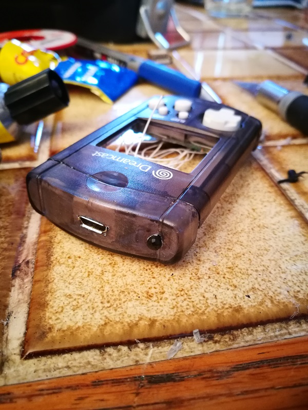
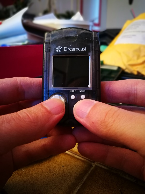
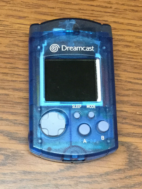
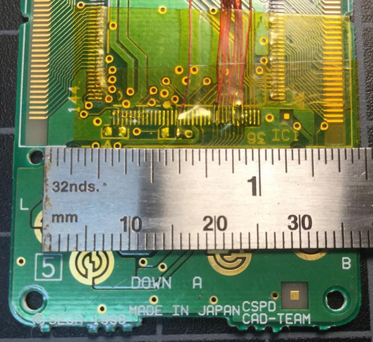
                  USB charging port, and homemade home button.

                  0_1497030520261_IMG_20170609_192529.jpg

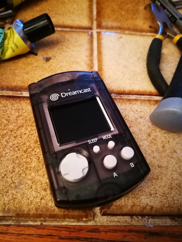
                  Final mock-up (I broke the screen when I tried to take the pcb apart, I need to buy another one)

                  0_1497030567226_IMG_20170609_192540.jpg

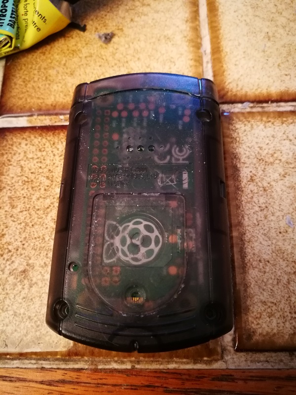
                  Pi logo was meant to go there !

                  0_1497030594721_IMG_20170609_193525.jpg

                  Everything fits, room for battery is about 30x30x5mm.

                  Next step is solder everything, as I'm not sure about the pinout for the screen, I didn't start yet.

                  obsidianspiderO 1 Reply Last reply Reply Quote 0
                  • obsidianspiderO
                    obsidianspider @Arvester
                    last edited by

                    @Arvester Looks great! Which battery are you going with? I'm thinking about picking up this 500mAh one from Adafruit which is 36mm x 29mm x 4.75mm once they get more Pi Zero Ws in stock (I want to make the most of their high shipping minimum).

                    πŸ“· @obsidianspider

                    1 Reply Last reply Reply Quote 0
                    • ArvesterA
                      Arvester
                      last edited by

                      I'll probably take this one too, those I was looking for on eBay are too thick.

                      Also, I would not recommand to put the home button in the corner as I chose, it prevents the VMU to close properly. I had to modify it, the cap is now glued to the top part of the shell, and I cut some bits of the shell's lower part so I can slide it inside the cap. I think there is more room on the sides since the pi is in the middle.

                      And could you please give me the pinout you used to connect the screen to the pi ? I have 8 pins, labelled LED, SCK, SDA, AO, RESET, CS, GND and VCC. The @moosepr 's signature's guide uses different pinout, and I have to admit that I understand absolutely NOTHING in electronics (so I'm proud to have reach this far without help ^^'). Thanks !

                      1 Reply Last reply Reply Quote 0
                      • ArvesterA
                        Arvester
                        last edited by

                        For the fun:
                        0_1497040765469_IMG_20170609_223349.jpg

                        1 Reply Last reply Reply Quote 1
                        • obsidianspiderO
                          obsidianspider @moosepr
                          last edited by

                          @Arvester I haven't attempted to wire one up after removing it from the board yet, but this is what @moosepr gave me as far as how to wire it up on the board. Tracing things through to figure out which pin on the screen matches up to the pins on the PCB shouldn't be too big of a deal. That will be my next step. Once I get that working I'll be sure to post up what I came up with.

                          @moosepr said in Pi in a Dreamcast VMU Build - WIP:

                          @obsidianspider lets see if i can fill in the blanks for you
                          1 - 3.3v
                          2 - gnd
                          3 - gpio 8 (pin 24)
                          4 - gpio 25 (pin 22)
                          5 - gpio 24 (pin 18)
                          6 - gpio 10 (pin 19)
                          7 - gpio 11 (pin 23)
                          8 - 3.3v (can be the same as pin 1)

                          my schematic is a little messy, lots of crossovers. tis something i need to refine

                          πŸ“· @obsidianspider

                          1 Reply Last reply Reply Quote 0
                          • mooseprM
                            moosepr
                            last edited by

                            here you go, a more fleshed out version

                            VCC - 3.3v
                            GND - gnd
                            CS - gpio 8 (pin 24)
                            RESET - gpio 25 (pin 22)
                            AO - gpio 24 (pin 18)
                            SDA - gpio 10 (pin 19)
                            SCK - gpio 11 (pin 23)
                            LED - 3.3v (can be the same as pin 1)

                            want to get a tft into your project, look no further than here https://retropie.org.uk/forum/topic/7464/ili9341-tft-screen-guide

                            1 Reply Last reply Reply Quote 1
                            • obsidianspiderO
                              obsidianspider
                              last edited by

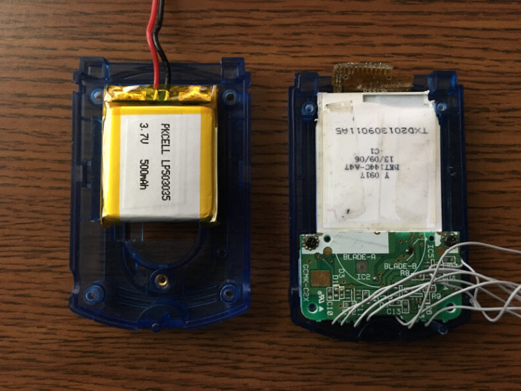
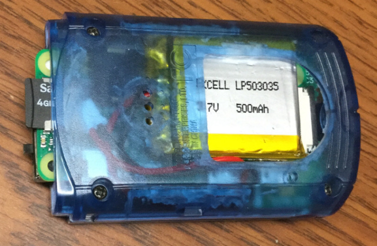
                              The big brown truck dropped off a little silver battery today. It looks like it's going to fit perfectly.

                              0_1497472506379_lipo1.jpg

                              0_1497472516982_lipo2.jpg

                              πŸ“· @obsidianspider

                              cellyC 1 Reply Last reply Reply Quote 1
                              • cellyC
                                celly @obsidianspider
                                last edited by

                                @obsidianspider awesome! Now get back to work!!

                                Currently Playing: Tetris (Gameboy)

                                1 Reply Last reply Reply Quote 1
                                • obsidianspiderO
                                  obsidianspider
                                  last edited by

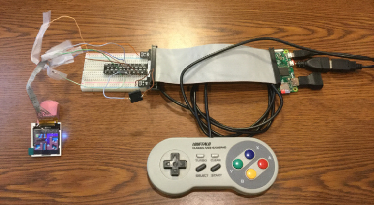
                                  After about four hours I managed to make some good progress in the garage today.

                                  • I removed the 1.44" TFT from the PCB, traced things out (the v2.1 screen has 13 pins, but the v1.1 screen only had 12), wired it up, and got it working.
                                  • I also hooked up one of the self-contained surface mount piezos and while it's not loud, it's pretty nice, and definitely better than silence.
                                  • I tested things out while connected to an actual Pi Zero instead of the Pi 2 that I'd been using for most of my testing. I remember now how slow those things are, but for what this toy will be, a novelty, it's totally fine.

                                  0_1497731800054_vmu-test-2017-06-17.jpg

                                  I made a brief test video so you can get an idea of the sound quality of the piezo. This is with the mixer set to 100%.

                                  I still haven't tested with the buttons and the screen and the piezo all at once on my test Pi Zero, but I'm not too worried about that. I also haven't tested running things directly from a LiPo, but @moosepr has proven multiple times that that's not an issue, so instead of reworking my test rig to try to prove out those things I'm going to move on to trying to fit things into the case as nicely as possible. Luckily I have two of those blue VMUs to test with before I do it "for real" with one of the off-white VMUs that @celly gave me.

                                  πŸ“· @obsidianspider

                                  1 Reply Last reply Reply Quote 2
                                  • obsidianspiderO
                                    obsidianspider
                                    last edited by obsidianspider

                                    Ah! Someone on YouTube already finished one!

                                    The screen fits really well, and the audio is really nice too. I wonder what the inside looks like...

                                    πŸ“· @obsidianspider

                                    1 Reply Last reply Reply Quote 2
                                    • obsidianspiderO
                                      obsidianspider
                                      last edited by

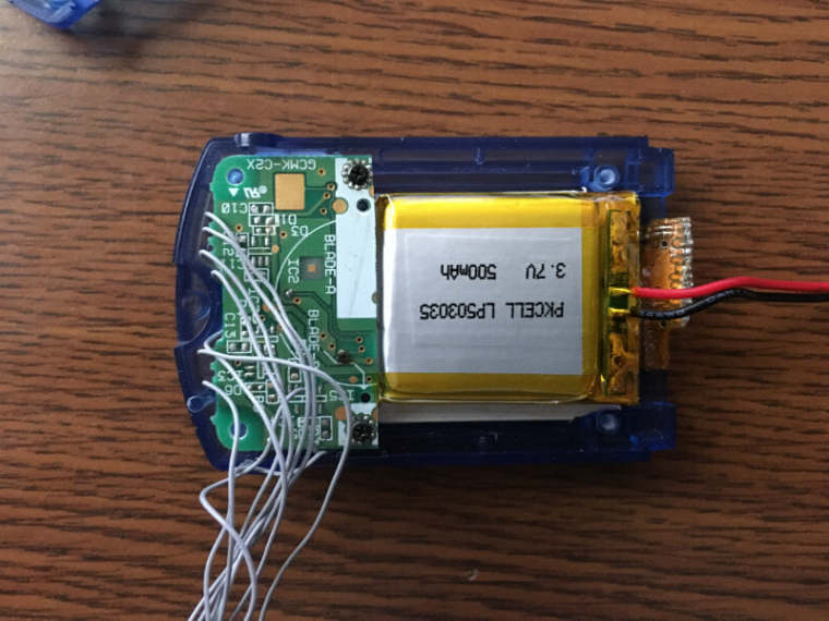
                                      It's uncomfortably tight, but I managed to fit all the components inside, without wires.

                                      0_1497742177314_vmu-test.jpg

                                      0_1497742187087_vmu-test-1.jpg

                                      0_1497742196394_vmu-test-2.jpg

                                      0_1497742205330_vmu-test-3.jpg

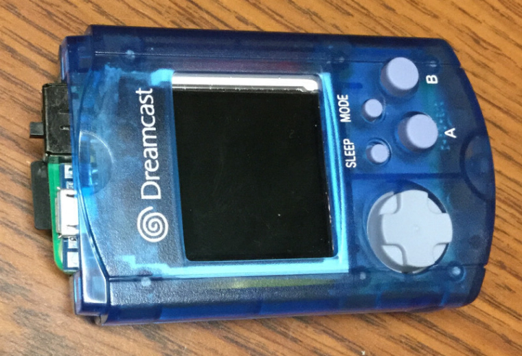
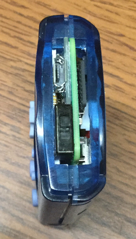
                                      I want to do some more fiddling with things, but after 7 hours of working on this today, I'm a bit fried. I don't want to go breaking something.

                                      πŸ“· @obsidianspider

                                      cellyC 1 Reply Last reply Reply Quote 2
                                      • cellyC
                                        celly @obsidianspider
                                        last edited by

                                        @obsidianspider yours will be fine. The test fit looks good to me. πŸ‘

                                        Currently Playing: Tetris (Gameboy)

                                        1 Reply Last reply Reply Quote 1
                                        • obsidianspiderO
                                          obsidianspider
                                          last edited by

                                          With things being a bit too snug with the IDE cabling I was using for button connections I went another route and tried using some magnet wire. It took all day, but I think I have it. Today I'll be trying to connect everything up to a test Pi to ensure functionality (including the battery, switch, charging board) before I smoosh it back into a case.

                                          0_1504523810152_Screen Shot 2017-09-04 at 7.14.46 AM.png

                                          πŸ“· @obsidianspider

                                          1 Reply Last reply Reply Quote 1
                                          • obsidianspiderO
                                            obsidianspider
                                            last edited by

                                            Today I managed to test all of the components outside the case, and everything works with my test Pi. Running off the battery without a booster works just fine with a Zero.

                                            0_1505063029610_Photo Sep 10, 11 32 33 AM.jpg

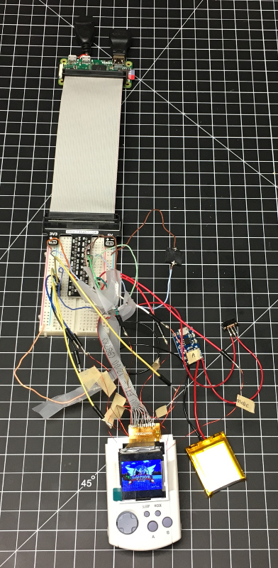
                                            Cranking up the volume in RetroArch makes the piezo loud enough to hear for general gaming, even if it's not quite high fidelity.

                                            Everything plays really nicely now that I'm using the board where I soldered to the chip pads instead of the old "make your own test pad" method.

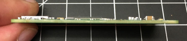
                                            Next up I need to make everything fit in the actual case. First up, removing unnecessary stuff from a Pi Zero. This looks awful, but it works. If anyone has tips on removing the USB ports, HDMI port, or camera connector in a cleaner manner, please let me know.

                                            0_1505063223272_Photo Sep 10, 12 53 15 PM.jpg

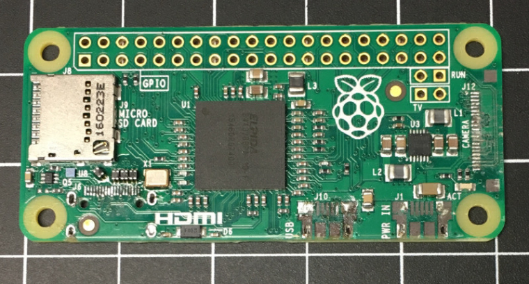
                                            Every little bit of thinness is going to help with this build.

                                            0_1505063257077_Photo Sep 10, 12 56 11 PM.jpg

                                            πŸ“· @obsidianspider

                                            1 Reply Last reply Reply Quote 2
                                            • First post
                                              Last post

                                            Contributions to the project are always appreciated, so if you would like to support us with a donation you can do so here.

                                            Hosting provided by Mythic-Beasts. See the Hosting Information page for more information.